
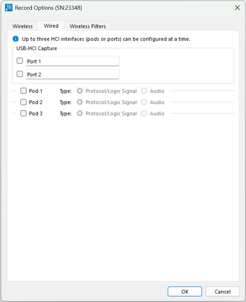
Initially, without any pod selected for capture, the dialog will appear in a compressed state. Selecting a pod for capture will open the pod’s options.
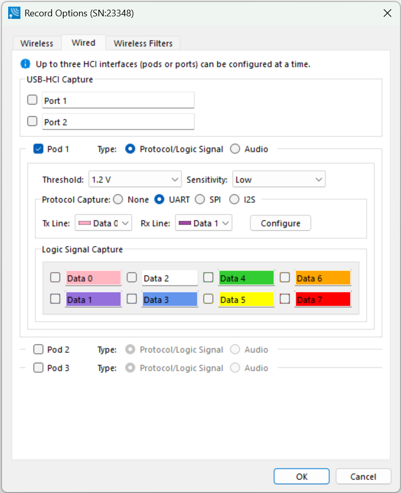
When all pods are selected for capture, the dialog is scrollable.
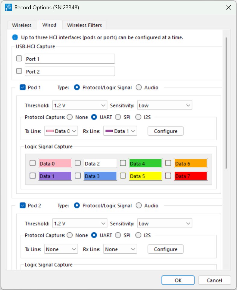
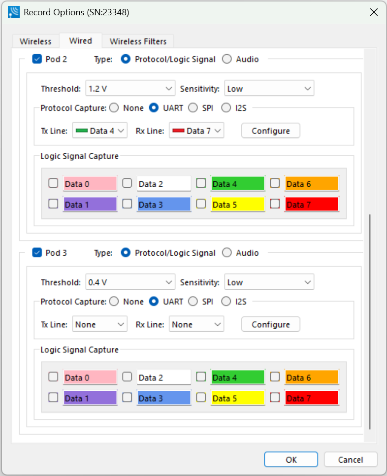
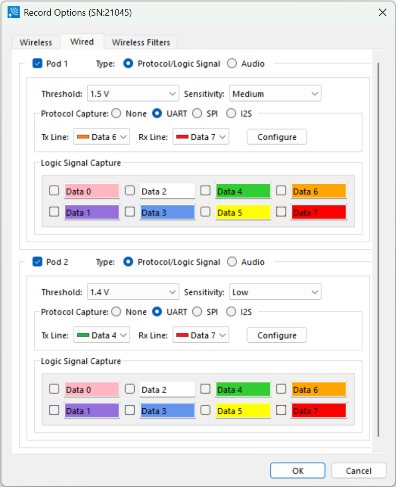
Record Options Wired Tab Selections
|
Pod Selection |
Section |
Description |
|
|
Pod 1, Pod 2, or Pod 3 |
|
When checked, the Pod is enabled for both Logic Signal and HCI capture. |
|
|
Threshold (V) |
Threshold voltage at which a line is in an ON state. The default value is set at 1.2 V (recommended). Users can select threshold value starting at 0.4 V and go up to 2.7 V. Using a value that’s close to half the signaling level will work for most applications. Please check your hardware datasheet or vendor to learn about the settings to use. |
||
|
Sensitivity |
Sensitivity to changes in voltage level around the threshold voltage. The default value is set to "low" (recommended) indicating lowest sensitivity to noise or maximum hysteresis. Please check your hardware datasheet or vendor to learn about the settings to use. |
||
|
HCI Capture Method: UART |
Tx line |
Data line selected for UART transmit |
|
|
Rx line |
Data line selected for UART receive |
||
|
Configure |
HCI UART I/O Settings. See HCI-UART I/O Settings following this table. |
||
|
HCI Capture Method: SPI |
Mode |
SPI Mode 0 – 3. |
|
|
CLK |
Data line selected for clock signal. |
||
|
MISO |
Data line selected for central output central input. |
||
|
MOSI |
Data line selected for central input central output. |
||
|
SS/CS |
Data line selected for central select signal. |
||
|
HCI Capture Method: I2S |
SCLK |
Data line selected for clock signal. |
|
|
FS |
Data line selected for frame sync signal. |
||
|
DC |
Data line selected for serial data signal. I2S is not supported by X240 in Dual Mode. |
||
|
Logic Signal Capture |
0-7 |
These are Logic Signal data lines 0-7 corresponding to Data 0- Data 7 on the Logic Analyzer Pod. When any data lines are selected, logic signal transitions on those lines will be captured. None or one or any number of data lines can be selected. |
|
|
|
Audio Capture |
|
Input Source Input 1 and 2 Desired Sample Rate Actual Sample Rate – determined based on desired setting and HW capabilities Sample Size Use Microphone (Mic Bias) |
Editable Signal Line Names
USB-HCI Capture
The line names for Port 1 and Port 2 may be edited to have custom names of up to 32 characters. A right-click on either control will display a menu to restore either the specific line name to default or restore all line names to default.
Pod 1 and Pod 2 HCI Capture Methods
The line names in the HCI Capture Methods UART, SPI and I2S selection controls for Pod 1 and Pod 2 may be edited. A right-click on any line-selection control will display a menu to edit the line-name selections, restore the specific line name to default, or restore all line names to default. Selection of the option to edit line-name selections will display a dialog for specifying custom line names of up to 32 characters.
Pod 1, Pod 2 and Pod 3 Logic Signal Capture
The logic signal line names in the Logic Signal Capture methods for Pod 1, Pod 2 and Pod 3 may be edited to have custom names of up to 32 characters. A right-click on any line-selection control will display a menu to restore the specific line name to default or restore all line names to default.
HCI UART I/O Settings
After clicking on the Configure button, the I/O Settings for UART can be configured without an HCI pod being connected to the analyzer. When you click on the OK button the configuration information is saved but is not stored on the analyzer.
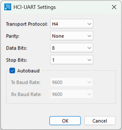
HCI UART Settings Definitions
|
Setting |
Value |
Description |
|
Transport Protocol |
H4 |
The simplest protocol designed to operate over RS-232 with no parity in a 5-wire configuration. |
|
BCSP |
BlueCore Serial Protocol, developed by CSR, provides a more reliable alternative to H4. The protocol is defined to run a 3-wire connection and can optionally use a 5-wire UART connection with two flow control lines. |
|
|
3-Wire (H5) |
A 3-wire protocol that provides error detection and correction. |
|
|
MWS WCI- 2 |
The Wireless Coexistence Interface (WCI) is a full duplex UART carrying logic signals framed as UART characters. |
|
|
Parity |
None |
No parity check occurs |
|
Even |
The count of bits set is an even number. |
|
|
Odd |
The count of bits set is an odd number. |
|
|
Data Bits |
8 |
The number of data bits in the expected packet. |
|
7 |
||
|
6 |
||
|
5 |
||
|
Stop Bits |
1 |
The number of data bits held in the mark (logic 1) condition at the end of the expected packet. |
|
1.5 |
||
|
2 |
||
|
Autobaud |
|
The analyzer can automatically determine the baud rate of the HCI UART when the Autobaud is selected. When the Autobaud checkbox is checked in the “HCI-UART Settings” dialog box the analyzer automatically determines the baud rate. Once a baud rate has been determined, it is applied to both the TX and RX lines. The baud rate is continually monitored during the capture and automatically adjusted if the baud rate of the received data changes. If Autobaud is used on multiple pods simultaneously then Autobaud determines the baud rate of each pod independently of the other pods. Additionally, if Autobaud is being used, other pods can still use fixed baud rates. It is possible, when starting the baud search, very short packets may be missed. |
|
TX Baud Rate |
Disabled |
The baud rates displayed are nominal baud rates as opposed to the precise values internal to the analyzer which may differ slightly with a mean absolute average difference of less than half a percent. If autobaud is used the difference may be more depending on how much the actual baud rate differs from those listed in the table. |
|
9,600 |
||
|
14,400 |
||
|
19,200 |
||
|
28,800 |
||
|
38,400 |
||
|
57,600 |
||
|
115,200 |
||
|
230,400 |
||
|
460,800 |
||
|
921,600 |
||
|
1,000,000 |
||
|
1,250,000 |
||
|
1,500,000 |
||
|
1,750,000 |
||
|
2,000,000 |
||
|
2,250,000 |
||
|
2,500,000 |
||
|
2,750,000 |
||
|
3,000,000 |
||
|
3,250,000 |
||
|
3,500,000 |
||
|
3,750,000 |
||
|
4,000,000 |
||
|
RX Baud Rate |
|
Same as TX Baud Rate. |