
Security information for the Wi-Fi, 802.15.4, and Matter protocols is configured in the Security Keys window. The window is opened using the Security Keys button on the main toolbar or by selecting “Security Keys” from the View menu.

802.15.4 Security Keys
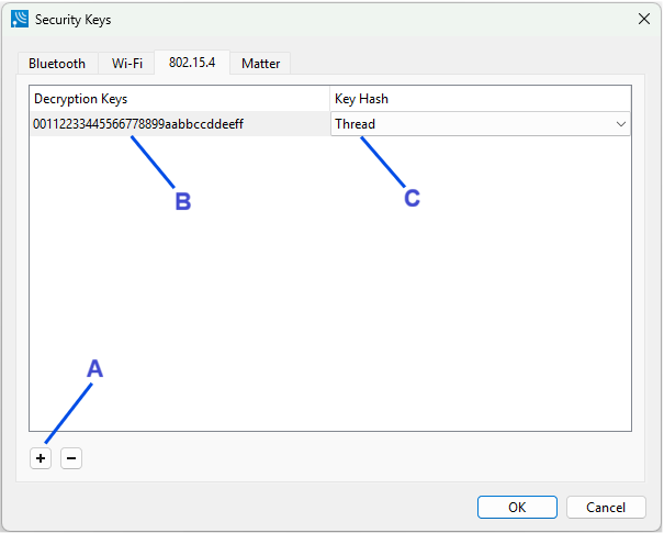
Once the window is open select the 802.15.4 tab to add a key.
-
Select add a new key (A).
-
Enter the key into the key value text box (B).
-
Select the key hash type (C). Currently the choices are “No Hash” and “Thread”. The Thread hash type should be selected for the Thread protocol.
Wi-Fi Security
Security information is provided in the Wi-Fi Security Window.
The window is opened using the Security Keys button on the main toolbar.
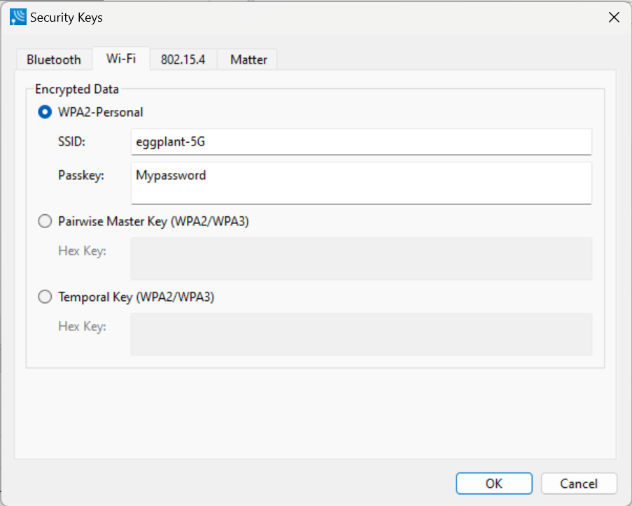
In the Wi-Fi Security dialog, select the encryption method being used with your device under test (DUT) by clicking on the radio button in the Encrypted Data section.
WPS software does not support WPA decryption that is based on the Temporal Key Integrity Protocol (TKIP). It does support WPA2 decryption based on the Advanced Encryption Standard (AES).
Wi-Fi Encrypted Data Options
|
Encrypted Data Option |
Field |
Description |
|
WPA2 - Personal |
SSID |
The station ID of the 802.11 communications link. |
|
Passkey |
The shared passkey phrase used in communications. |
|
|
Pairwise Master Key |
key |
The key is established between the wireless station and the access point. The key size is 32 Bytes for WPA2, the key size is 48 bytes for WPA3. |
|
Temporal Key |
|
A temporary key used to encrypt data for only the current session. |
Wi-Fi Decryption
Starting with Wireless Protocol Suite 3.00 release, to use the Wi-Fi Decryption functionality you need to go through a one-time install of a separate Wi-Fi decryption license key software.
To find out if the key is enabled, in the Wireless Protocol Suite open the ‘Security Keys’ dialog and go to the ‘Wi-Fi’ tab. The message at the bottom suggests whether the Wi-Fi decryption functionality is enabled or not. See below instructions on how to obtain the key.
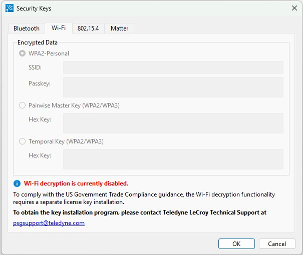
To obtain the key installation program, please contact Teledyne LeCroy Technical Support at User Support with the following information. Please detail which software you are requesting as well as your complete contact information in English shown below.
-
Given/First Name
-
Family/Last Name
-
Company
-
Work E-Mail
-
Work Phone
-
Work Address
-
Country
-
Address
-
City
-
Zip Code
-
Once your information is verified our support team will contact you and provide details for obtaining the key installation program.
You would need to install the key only once for all future Frontline Wireless Protocol Suite releases. This information is also included in the tooltip.
Entering Wi-Fi decryption license key
After the program is installed, click on File in the main toolbar and select Activate Wi-Fi Decryption….
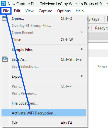
An “Open” window is displayed. Navigate to the location of the license key and enter the key. After successfully entering a valid key, Wi-Fi decryption is enabled.
Wi-Fi Device Scanner
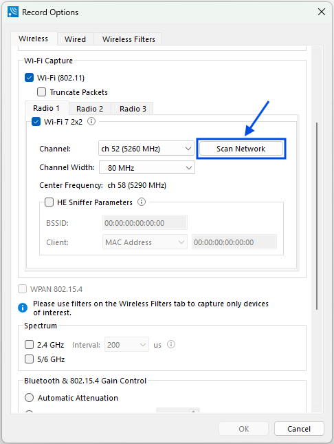
On the Record Options dialog Wireless tab, click on Scan Network button.
The Wi-Fi Device Scanner dialog will open.
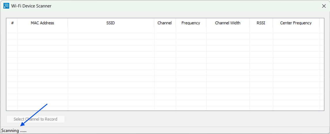
Scanning begins automatically when the dialog opens. Status is displayed in the lower left of the dialog.
The X700 uses antennae Wi-Fi 1a and Wi-Fi 1b for Wi-Fi scanning. X500/X500e uses Wi-Fi Rx1 and Wi-Fi Rx4.
When scanning completes, the dialog is populated and the status in the lower left of dialog shows “Scan Finished”.
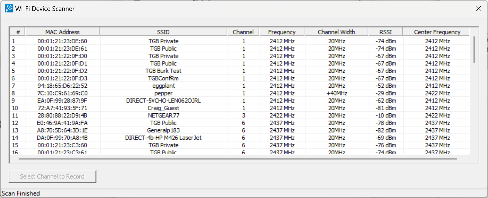
The Wi-Fi Device Scanner dialog displays a list of discoverable Wi-Fi devices in a table. The devices are identified by:
-
MAC Address
-
SSID
-
Channel
-
Frequency
-
Channel Width
-
RSSI
-
Center Frequency
Click on the device that you want to monitor and it will become highlighted.
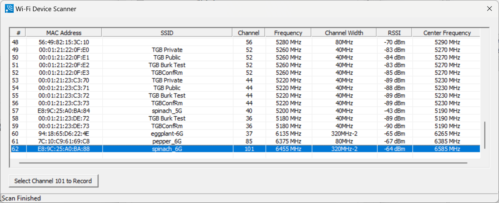
Click the Select Channel <#> to Record button in lower left of dialog to set the Primary Channel and Channel Width settings in the Record Options dialog Wireless tab.
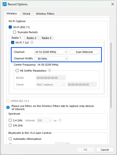
Click OK button to save settings and close Record Options dialog.
If you changed the Primary Channel and Channel Width settings by selecting a device in the Wi-Fi Device Scanner dialog and do not want to keep the setting changes, you can click on the Cancel button to discard the settings and close Record Options dialog. You can also manually select a different Primary Channel and/or Channel Width setting from the drop-down list for each setting.
Matter Security Configuration
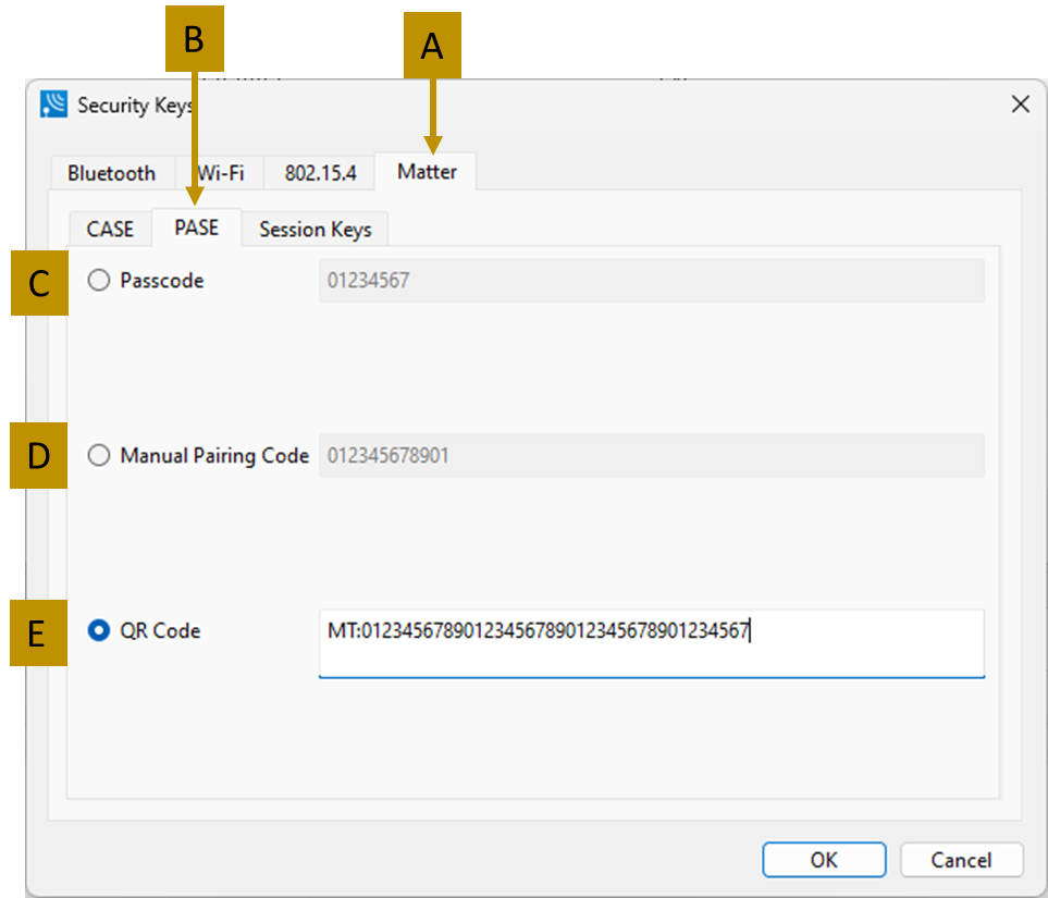
The Matter security configuration consists of the optional setting of the Passcode-Authenticated Session Establishment (PASE) security information, the Certificate Authenticated Session Establishment (CASE) security information, and the session keys. Not setting the PASE or CASE information will not affect the decryption process if the appropriate session keys are included. All Matter security configuration settings are accessible from the Matter tab (see below).
To access the PASE settings, select the Matter tab (A). The PASE tab (B) contains the security configuration and only one of the settings is active at a time which is selected by the radial button. The options are: Passcode digits for a single device (C), a Manual Pairing Code composed of digits (D), or a QR code which starts with MT: and uses base 38 encoding (E). Not setting the PASE information will not affect the decryption process if the appropriate session keys are included.
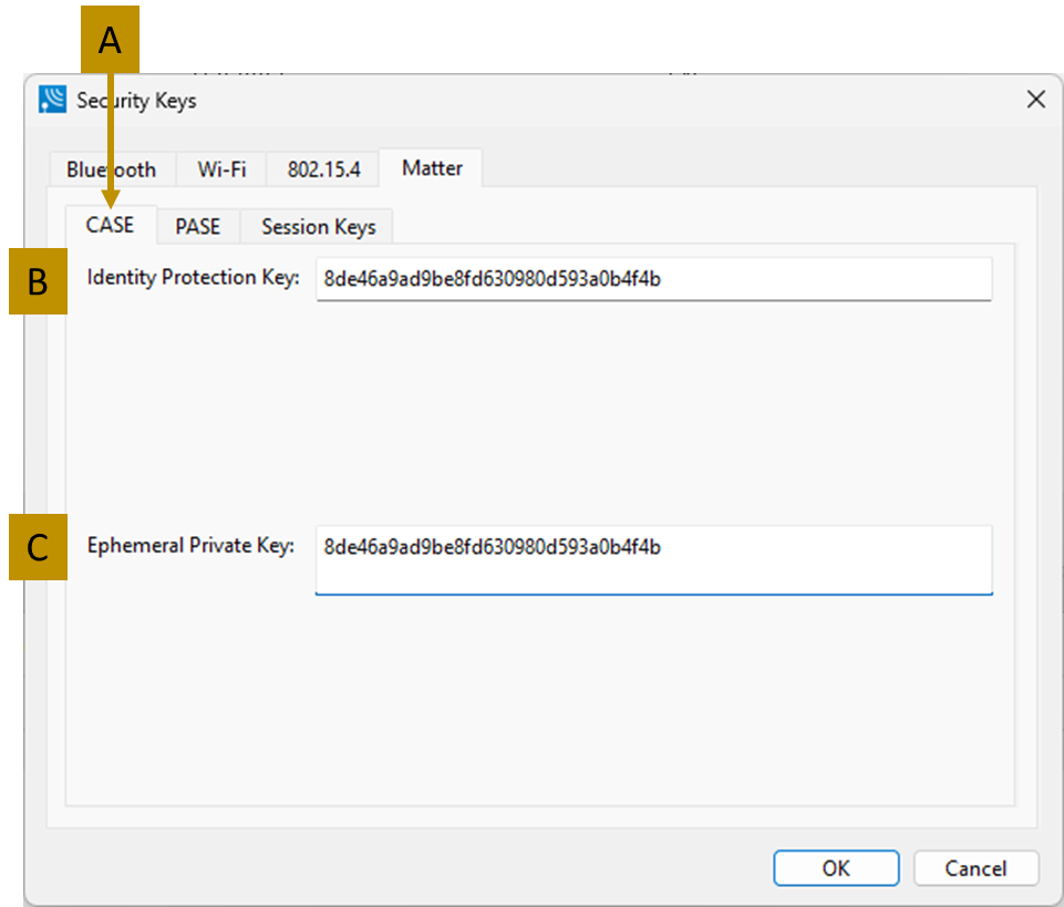
The CASE (Certificate Authenticated Session Establishment) settings (below) are used in the commissioning process for the Matter protocol. All CASE settings are accessible from the Matter tab. The CASE tab (A) contains security configuration options. These are the:
-
Identity Protection Key (B): A 128-bit key consisting of 32 hexadecimal characters.
-
Ephemeral Protection Key (C): A 128-bit key consisting of 32 hexadecimal characters.
Not setting the CASE information will not affect the decryption process if the appropriate session keys are included.
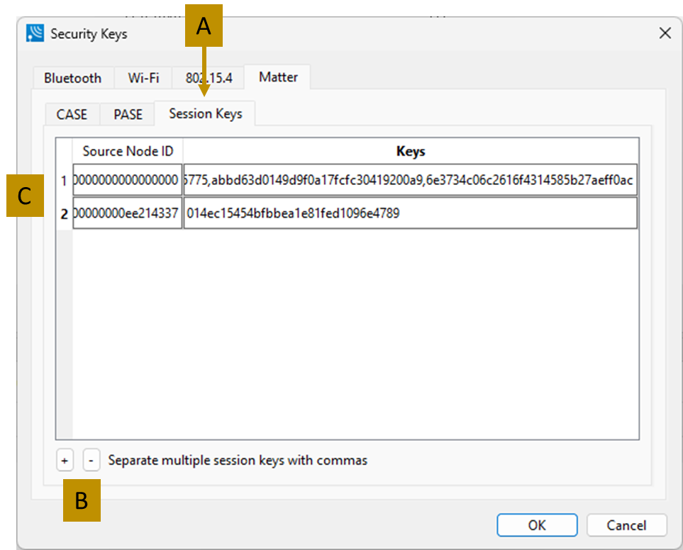
The 128-bit session keys are used to encrypt and decrypt Matter messages. These keys are used along with the 64-bit Source Node ID which is part of the encryption nonce. Both are needed by WPS for Matter message decryption. All session key settings are accessible from the Matter tab.
To access the session key settings, select the Session Keys tab (below) which contains the security configuration settings. To add and remove session keys and their corresponding Source Node IDs, use the “+” button (B) to add them and to remove them, select a row and using the “-” button. The 64-bit Source Node IDs are entered as 16 hexadecimal characters, and the 128-bit Session Key is entered as 32 hexadecimal characters (C). Multiple session keys can be entered, separated by commas (no spaces). Modification of the key information is done by editing the rows directly. The following test keys do not need to be entered because they will always be tried. They are the:
-
Initiator-to-Responder Test key: 5EDED244E5532B3CDC23409DBAD052D2
-
Responder-to-Initiator Test key: A9E011B1737C6D4B70E4C0A2FE660476
Wi-Fi Device - MAC Address Editor
If you know the MAC Address of the device, you can enter it manually.
-
From the Settings dialog select the "Edit" button.
-
On the MAC Address Editor enter the MAC Address for the device.
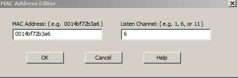
-
Enter a channel number in Listen Channel.
-
Select "OK".
The MAC Address appears on the Settings dialog.
Once you close the dialog, the last MAC Address shown will appear when you reopen the dialog.
Determining Central and Peripheral
In Bluetooth, the device that initiates the connection is always the central at connection time. You only need to know the central and peripheral at connection time when setting up the I/O Settings. Afterward, a role switch may occur, but the analyzer automatically follows the role switch.
You do not have to identify a Central address if you are using Firmware Version 62 or newer.
Role Switches
After the connection has been made, a role switch can take place. A good example of why this happens would be when a mouse connects to the PC. The mouse initiates the connection, so it is the central. After the connection is made, a role switch occurs so that the PC becomes the central and the mouse becomes a peripheral. The role switch takes place because the PC may be working with multiple devices at the same time. Therefore, the PC would not be a peripheral of more than one device.
Let us say that a link exists between a PC and a keyboard with the PC as central. If the mouse wants to become a member of the link, it initiates the connection. Since the mouse initiated the connection, it is the central of a new link and the PC is the peripheral. The PC is still the central of the link between the PC and keyboard. A role switch now occurs between the PC and the mouse, and the PC is now the central of a link with two peripherals: the mouse and keyboard.
Classic Bluetooth Transmitter Classes
Classic Bluetooth transmitters are categorized by power classes, that is, by the amount of RF power output. A Bluetooth Class maximum operating range is directly related to the power output. The class is important in conductive testing because the DUTs and the Frontline analyzer are connected directly to each other, usually over small distances. The absence of power loss, which occurs during over-the-air transmission, means that larger than normal power levels may be present at the receiving port. Attenuation may be necessary to protect both the DUT and the Frontline analyzer from excessive power input and to ensure reliable operation.
The table below lists the maximum power and operating range for each Classic Bluetooth Class.
Classic Bluetooth Power Classes
|
Class |
Maximum Power |
Operating Range |
|
1 |
100 mW (20 dBm) |
100 meters |
|
3 |
1 mW (0 dBm) |
1 meter |
Good engineering judgment is essential to protecting both the Frontline Bluetooth analyzer and the devices under test from power levels that could cause damage. The procedures contained here are general guidelines for connecting the equipment for conductive testing.
Caution: Bluetooth Low Energy Transmitter
A Bluetooth Low Energy device’s maximum operating range is directly related to the power output. The power output is important in conductive testing because the DUTs and the Frontline unit are connected directly to each other, usually over small distances. The absence of power loss, which occurs during over-the-air transmission, means that larger than normal power levels may be present at the receiving port. Attenuation may be necessary to protect both the DUT and the Frontline unit from excessive power input and to ensure reliable operation.
The table below lists the maximum power and operating range for Bluetooth Low Energy transmitters.
Bluetooth Low Energy Transmitter
|
Bluetooth SIG Specification |
Maximum Power |
Operating Range |
|
Up to 4 |
10 dBm (5 mW) |
50 meters |
Good engineering judgment is essential to protecting both the Frontline Bluetooth analyzers and the devices under test from power levels that could cause damage. The procedures contained here are general guidelines for connecting the equipment for conductive testing.
Conductive Testing
Conductive testing could be used for many reasons, but the most common use is to isolate the Bluetooth or Wi-Fi test setup from the surrounding environment. Interference from radio frequency (RF) sources is the most common reason for isolating the test from the environment. This is especially important when the environment contains RF sources using the industrial, scientific, and medical (ISM) radio bands from 2.4 to 2.485 GHz that are the bands used for Bluetooth or Wi-Fi.
“Conductive” in this context means that you are not “air sniffing”, that is, capturing Bluetooth or Wi-Fi transmissions on the Frontline analyzer's antenna. The conductive test setup uses coaxial cable to directly connect the Device Under Test (DUT) to the analyzer's antenna connectors. The coaxial cable provides the isolation from the environment through shielding.
Test Equipment
While exact conductive test setups are dependent on the specific circumstances surrounding the DUT (Device Under Test) RF interface, the following equipment is required for most testing situations.
-
Coaxial cable with adapter for connecting to DUT 1.
-
Coaxial cable with adapter for connecting to DUT 2.
-
Coaxial T-connector.
-
SMA adapters for connecting coaxial cable or attenuators to the Frontline antenna connectors.
-
Attenuators, values depending on the Bluetooth technology or DUT power output levels.
-
Wideband Bluetooth Protocol Analyzer.
-
Personal computer for running Wireless Protocol Suite software.
Test Setup
The Figure below shows the conductive test setup. The values of AT1, AT2, and AT3 depend on the power transmitted by DUT 1 and DUT 2.
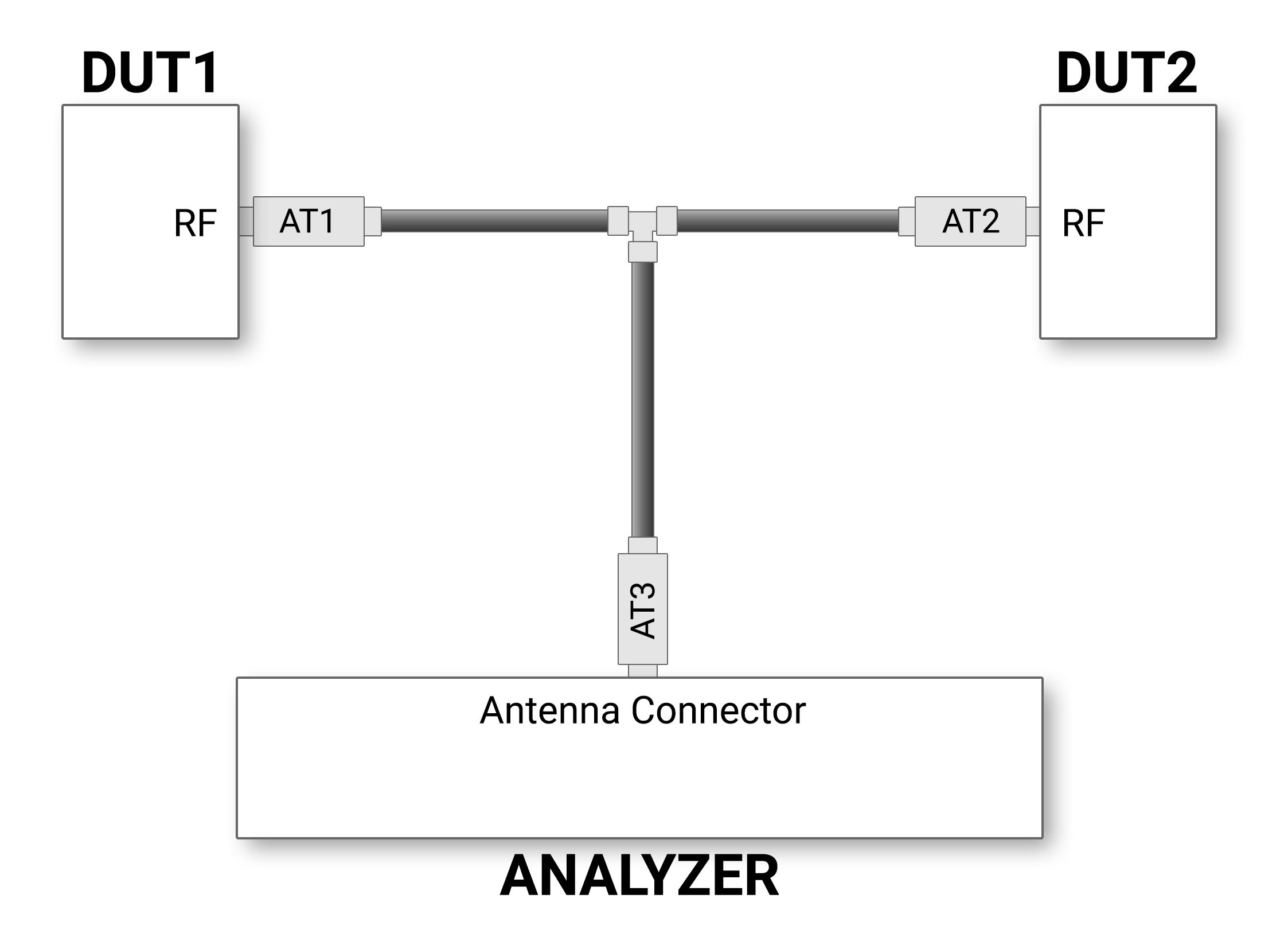
The AT1 through AT3 attenuator values will depend on the DUT1 and DUT2 transmitter Class or the transmit power from each device. At higher power levels, all three attenuators may be needed. In all cases, use good engineering practices to protect the devices under test and the analyzer from damage, to ensure reliable operation.
For example, assume that there is no attenuation in the test setup:
-
At the T-connector, the power will split in half. For example, if DUT1 is a Class 1 device transmitting +20 dBm (100 mW) (at the T-connector) the power will be split with +17 dBm (50 mW) going to DUT2 and +17 dBm (50 mW) going to the antenna connector. Adding additional attenuation with AT1, AT2, AT3, and the Record Options -> RSSI Threshold selection will further reduce the input power level to the analyzer radio.
-
If DUT1 or DUT2 is a Class 2 device, +10 dBm (12.5 mW) will reach the antenna connector. If they are Class 3 devices, -3 dBm (0.5 mW) will reach the antenna connector.
If the protocol analysis results prove to be unreliable, adjust the AT1, AT2, or AT3 values and the Record Option > RSSI Threshold settings to achieve reliable results.
Bluetooth Conductive Test Process
After connecting DUT1, DUT2, and the Frontline Bluetooth protocol analyzer hardware, follow these steps to capture Bluetooth data.
For the X500/X500e, the connection should be to BT Rx1.
-
Pair DUT 1 and DUT 2.
-
Establish data transmission between DUT 1 and DUT 2.
-
Begin capture of the data with the Frontline protocol analyzer.
-
Conduct protocol analysis with the Wireless Protocol Suite software on the personal computer or save the capture file for future analysis.