
The Device Settings window configures the External Trigger and Probe Calibration settings for each device supported by the Net Protocol Suite. For the M648, you can also set up the FEC counter. See M1288 Calibration, M648 Auto Calibration, and External Trigger for more information.
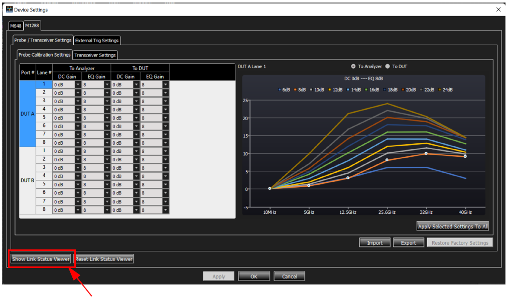
M1288 Device Settings
The Device Settings window configures the following:
-
External Trigger settings
-
Probe/Transceiver settings
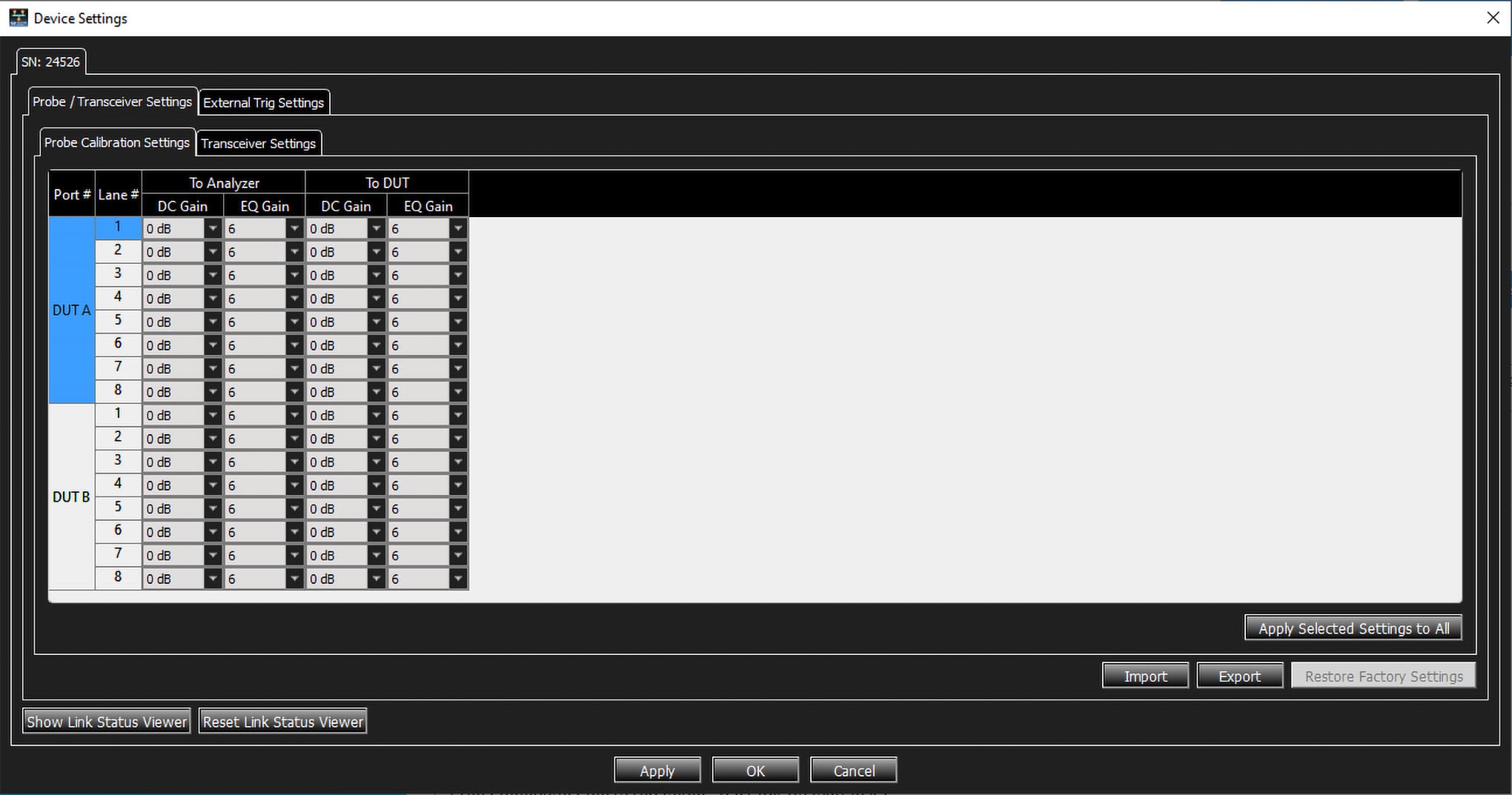
For the M1288, you can set the following parameters per Port and per Lane:
-
To Analyzer:
-
DC Gain
-
EQ Gain
-
-
To DUT:
-
DC Gain
-
EQ Gain
-
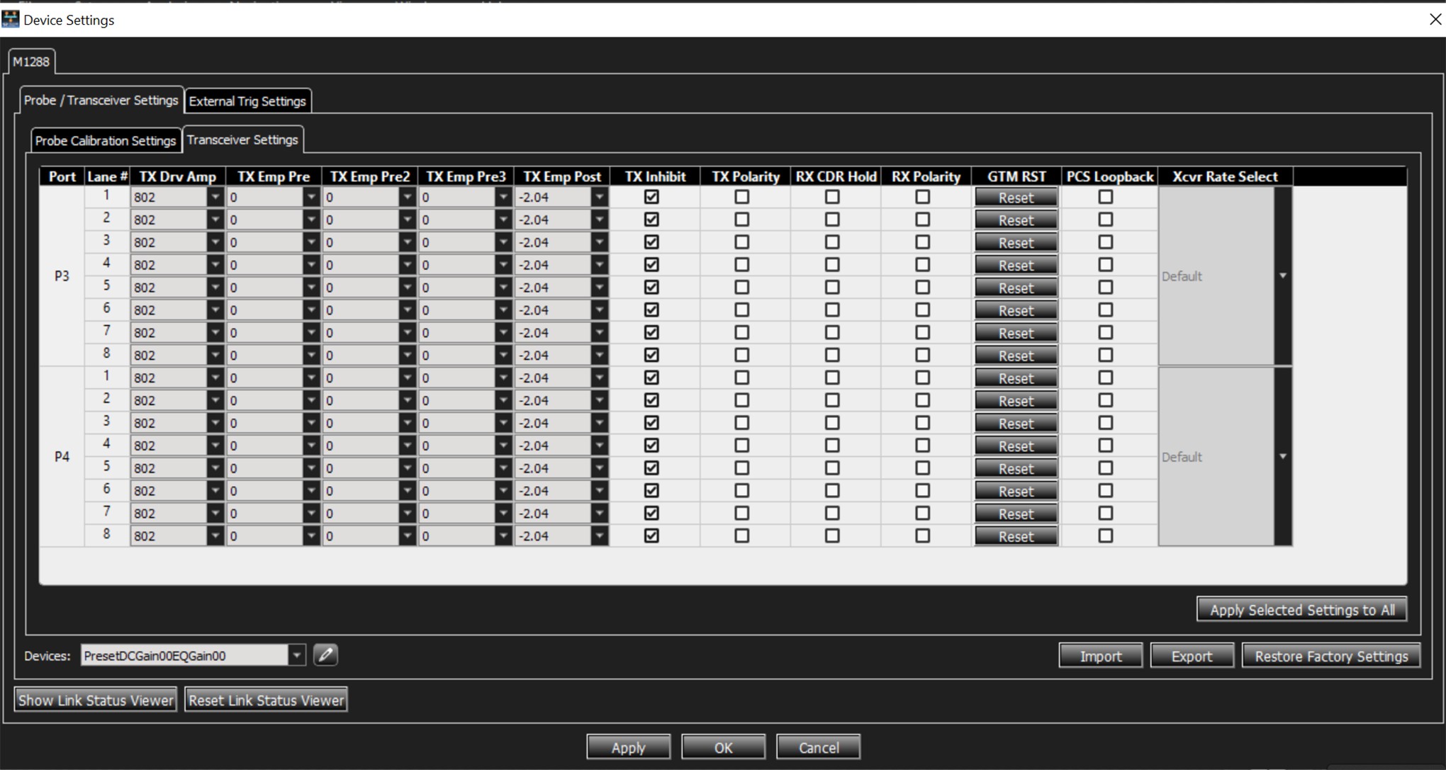
The following options are available for each lane of the M1288:
-
TX Drv Amp: 585 to 998
-
TX Emp Pre: 0 to -18.69
-
TX Emp Pre2: 0 to -7.09
-
TX Emp Pre3: 0 to -7.09
-
TX EMP Post: 0 to -18.69
-
TX Inhibit: On or Off
-
TX Polarity: Pos or Neg
-
RX CDR Hold: On or Off
-
RX Polarity: Pos or Neg
-
GTM RST: Reset
-
PCS Loopback: On or Off
-
Xcvr Rate Select: Default
The options are:
-
Apply the selected settings to all lanes
-
Import settings from a stored file
-
Export the current settings to a saved file for use in the future
-
Restore to Factory Settings
M1288 Auto Calibration
This feature calibrates the DUT path of the M1288 probe to work for your DUTs. It is needed in case your DUTs have trouble working with the defaults settings and the available presets of the Probe. Auto Calibration works in conjunction with a DUT BER script you provide to determine the best Probe Calibration Setting.
To perform auto calibration:
-
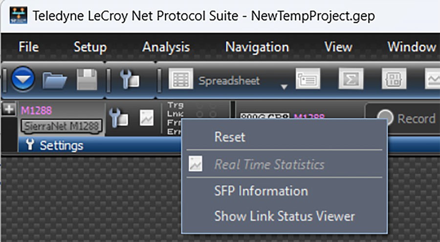
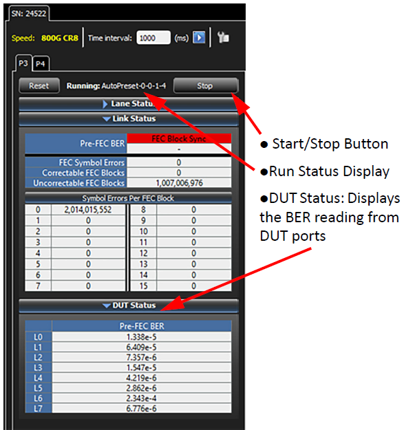
Open Link Status View: Right-click on the Project LED Status and select Show Link Status Viewer.
-
Configure Auto Calibration Settings:
-
Enable DUT BER Check must be enabled to run Auto Calibration for M1288
-
Enable LT Detection is not supported when DUT BER Check is enabled
-
Specify the Python script that provides your DUT BER measurements. Your script must provide an implementation of DutInterface. A script template, DutScriptTemplate.py, is available here: C:\Users\Public\Documents\LeCroy\Net Protocol Suite\DUTScript
-
Enable Range Filter allows you to define lower and upper limit values for calibration to sweep through for EQ Gain DUT and DC Gain DUT parameters.
-
-
Start Auto Calibration
-
Auto Calibration result: The process will automatically apply the settings to the Probe that yield the best BER for each DUT after the completion of Auto Calibration.
Special Considerations
M1288 auto calibration is only available for the DUT Path. Analyzer Path auto calibration is not available.
The Python path that is used to run the auto calibration DUT script needs to be specified at Preference >SW Settings > Python Path. The software will otherwise set any found installed Python as default.
Minimum required Python module for running DUT scripts:
-
websockets>=13.1
-
xoa-driver>=2.8.0
Minimum required Python version that supports the above module: Python >=3.8
M1288 Calibration
The M1288 probes come pre-calibrated and, in many cases, will not need additional field calibration. Following these instructions, along with using a worksheet to track the calibration settings, will help perform the field calibration. There are two calibrations possible:
-
DUT path calibration. This should be performed first, if necessary.
-
Analyzer path calibration.
M1288 DUT Path Calibration
Calibrate the DUT path first before proceeding to calibrating the Analyzer side of the probe.
-
To perform the DUT path calibration, you will need a SierraNet M1288 analyzer, the Net Protocol Suite software, and the M1288 Calibration spreadsheet.
-
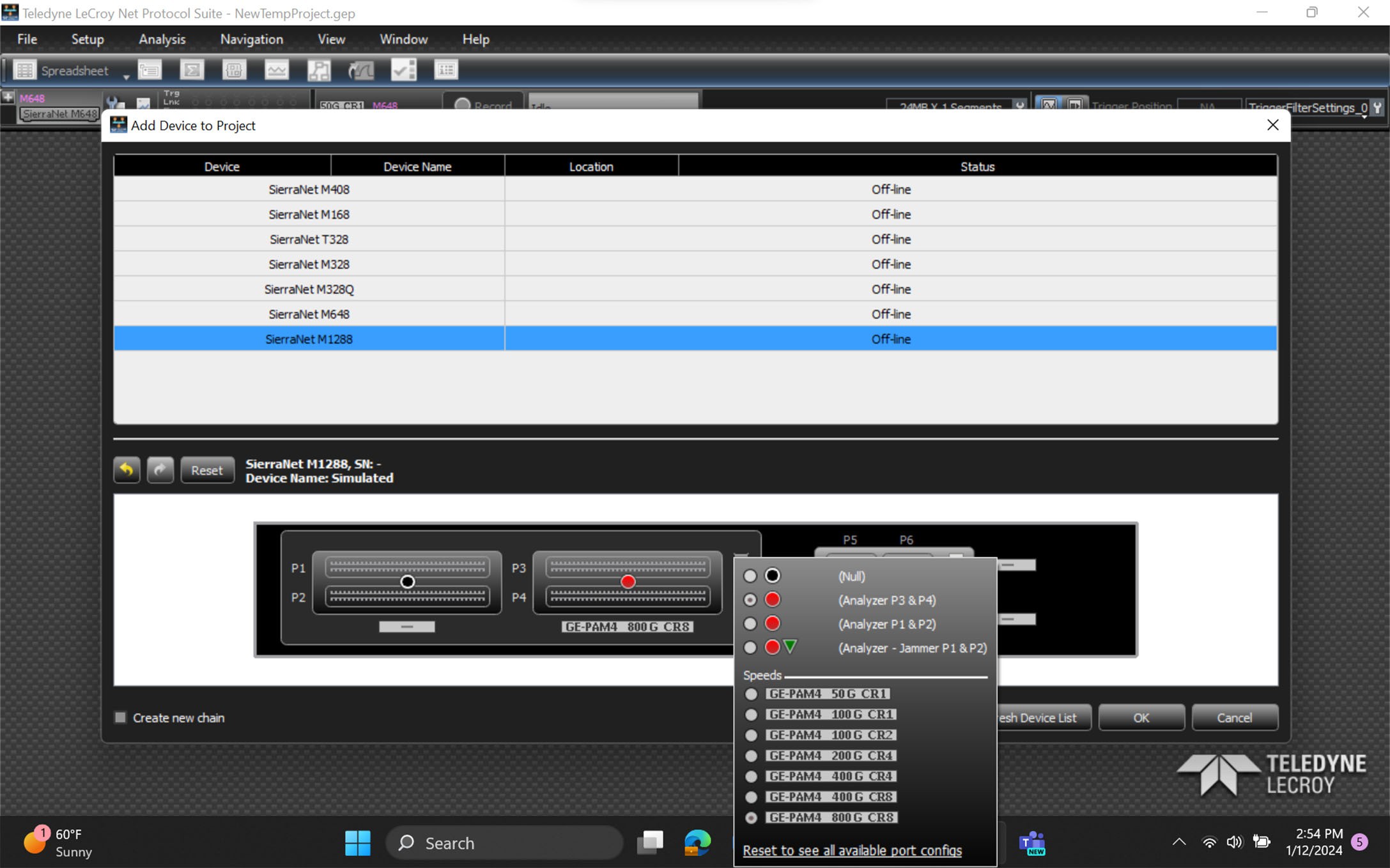
Connect and add the M1288 probe to the Net Protocol Suite software. The Add Device to Project window displays.
-
Configure ports P3 and P4 in 8x100G mode (if supported). This enables each lane to be calibrated independently. This also assumes that:
-
The DUT has a mechanism to read the BER values, OR
-
The DUT path doesn't need calibration, just the analyzer path. If the DUT path doesn't need calibration, skip to the M1288 Analyzer Path Calibration section.
-
Note: If one or more of the DUTs do not support a BER reading, contact [email protected] for assistance using the analyzer to assess the link quality.
-
Verify the probe middle ('Status') LED is flashing (you are connected to the probe). If the Status LED is Blue or Red, contact Support at [email protected].
-
Open the Device Settings window by clicking the wrench icon next to the device.
-
To find the quickest calibration setting, test the values in this order:
-
For 100G Base speeds: (0/8, 0/10, 0/12, -2/8, -2/10, -2/12) and
-
For 50G Base speeds: (0/16, 0/18, 0/20, -2/16, -2/18, -2/20) .
-
If the goal is to find the best calibration settings, then run through more settings (possibly skipping the -4 setting).
-
Change one value at a time, so in a thorough search, start with 0/6 and move up to 0/24, once at 0/24, the process can begin again at either -2/24 and work down or -2/6 and work up.
-
-
Enter the BER reading in the spreadsheet for any lanes that come up with a BER reading. Once the calibration is complete, the table automatically marks the lowest BER in each row as green, therefore identifying the best setting .
-
By changing all lanes to the same setting, all the values can be quickly tested and then the spreadsheet will show the best setting for each individual value. The DUT Calibration - Example tab in the Calibration Workbook should help make it clearer how the process works.
-
For lanes that don't come up, leave the field blank.
M1288 Analyzer Path Calibration
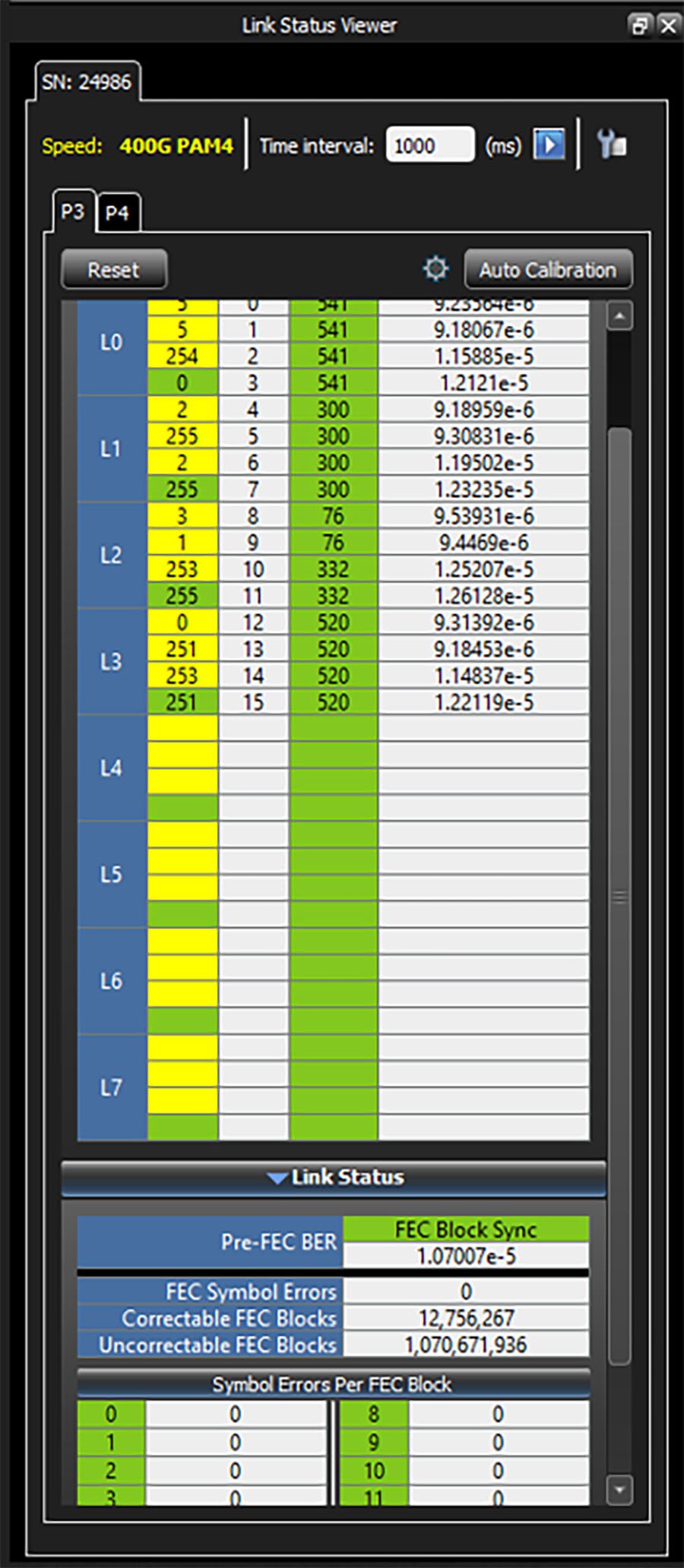
Once the lanes are showing good at the DUT side and the links are up (with valid PCS traffic running), calibrate the Analyzer path, as needed. The Link Status dialog makes this easy:
-
Click the Show Link Status Viewer button in the Device Status window.
-
The Link Status window displays on the main Net Protocol Suite window, below.
-
For calibrating the analyzer path, detect lanes that have higher BER, and manipulate them one by one, in a similar manner to the DUT path described above in M1288 DUT Path Calibration.
M648 Device Settings
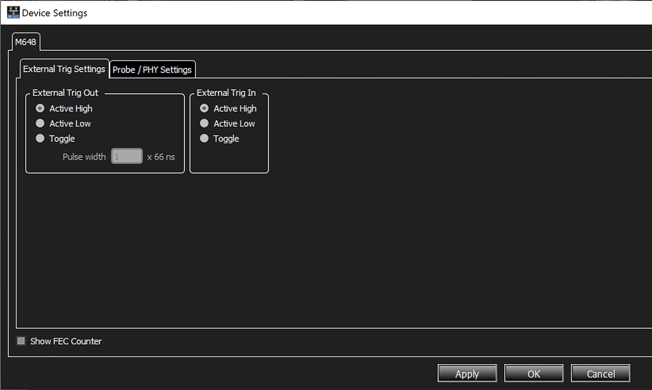
The Device Settings window configures the following:
-
External Trigger settings
-
Probe/PHY settings
-
Forward Error Correction (FEC) Counter settings
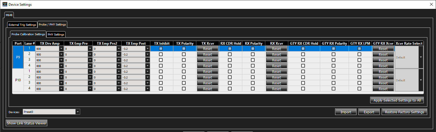
For the M648 Probe Calibration you can set the following options for each lane:
-
TX Drv Amp: 250 to 1025
-
TX Emp Pre: 0 to -9.2
-
TX Emp Pre2: 0 to -2.7
-
TX EMP Post: 0 to -9.2
-
TX Inhibit: On or Off
-
TX Polarity: Pos or Neg
-
TX Xcvr: Reset
-
RX CDR Hold: On or Off
-
RX Polarity: Pos or Neg
-
RX Xcvr: Reset
-
GTY RX CDR Hold: On or Off
-
GTY RX Polarity: Pos or Neg
-
GTY RX LPM: On or Off
-
GTY RX Xcvr: Reset
You can apply the selected settings to all lanes, Import settings from a stored file, Export the
current settings to a saved file for use in the future or Restore the Factory Settings.
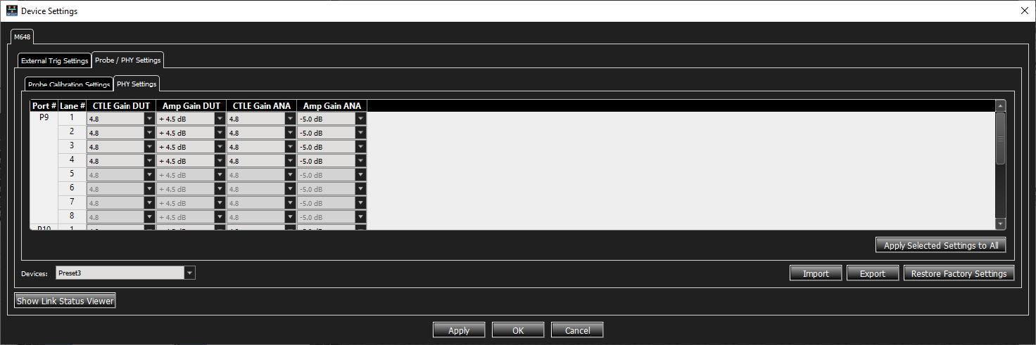
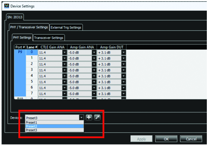
For the M648 you can set the following parameters per Port and per Lane:
-
CTLE Gain DUT
-
Amp Gain DUT
-
CTLE Gain ANA
-
Amp Gain ANA
For the M648 Probe and PHY Calibration settings, you can select Presets from the Devices drop-down list. You can also click the add button to add a new preset or save the current setting as a preset, or click the edit button to rename a selected preset.
M648 Auto Calibration
If you need to ease the process of finding a combination of Probe Settings that will result in a clean link, you can use the Auto Calibration option. This process first goes through all available known Presets to determine if one of them results in a clean link. If not, it will then loop through all possible combinations of Probe Settings, until it finds a setting that does.
This is found by clicking the Show Link Status Viewer button on the Device Settings window, shown below. To use Auto Calibration, click Auto Calibration. The icon to the left of the Auto Calibration button changes to yellow when the first possible calibration value is found, then changes to green when the best calibration value is found.
This process can be lengthy, as there are 73 x 8 x 8 = 4672 potential cases to try. The time each case takes is configurable; that is, the longer the Analyzer ‘dwells’ on each case, better results are produced. With the default dwell time, the worst-case Auto Calibration run could take up to 30 hours. However, in practice, most runs find adequate settings in between 30 minutes to 2 hours.
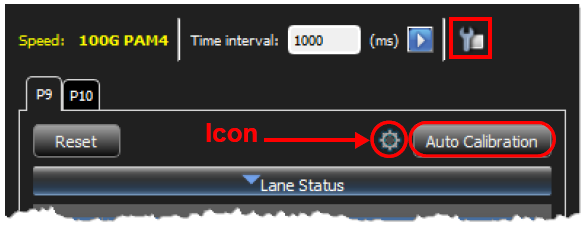
To change Auto Calibration settings, click the 
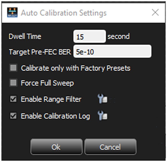
M648 Auto Calibration Settings
|
Setting |
Description |
|---|---|
|
Dwell Time |
The time (in seconds) the Auto Calibration process monitors the link stability and accumulates the Pre-FEC BER. Making this longer lengthens the total calibration time, but yields more stable settings. |
|
Target Pre-FEC BER |
During the Auto Calibration process, the BER found will be compared to this value to determine if the link is good enough. Making this smaller will lengthen the total calibration time, as more settings will be attempted in an effort to reach the lower BER. |
|
Calibrate only with Factory Presets |
Allows for a quicker calibration process, as the software will only attempt previously known settings, saved as Factory Presets. If none of these Presets satisfies the calibration in terms of link stability time or BER, the best Preset will be chosen and additional settings will not be attempted. When this is unchecked, if no Presets satisfy the calibration requirements, the Auto Calibration will go ahead to systematically attempt each combination of PHY settings variables, potentially taking many hours to complete. |
|
Force Full Sweep |
When the Auto Calibration process find settings that satisfy the required parameters in terms of link stability and BER, it will stop the calibration and use those settings. Checking this option will force the process to keep searching for even better results, until all combinations have been attempted. This will take many hours. |
|
Enable Range Filter |
Check this box to add range filters to the Auto Calibration. See M648 Range Filter. |
|
Enable Calibration Log |
Check this box to log results for each attempted setting. See M648 Auto Calibration Log. |
The following table shows how to use the various settings together. There are only certain combinations you can use to search for the best BER.
|
Combination |
Result |
|---|---|
|
Calibrate only with Factory Presets + Force Full Sweep |
Adding Force Full Sweep with Factory Presets forces the system to check all the factory presets for the best Pre-Fec BER (the set BER or below) instead of stopping when it finds the first instance. |
|
Calibrate only with Factory Presets + Enable Range Filter |
Invalid. The Range Filter will be ignored. |
|
Force Full Sweep + Enable Range Filter |
Adding Force Full Sweep with Enable Range Filter forces the system to check all the settings in the range for the best Pre-Fec BER (the set BER or below) instead of stopping when it finds the first instance. |
|
Calibrate only with Factory Presets + Force Full Sweep + Enable Range Filter |
Invalid. The Range Filter will be ignored. |
M648 Range Filter
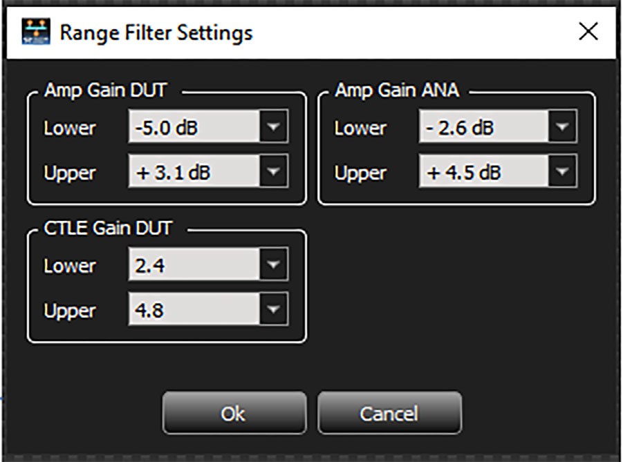
The Range Filter option allows you to choose a specific range in which to search for the Target Pre-Fec BER. You can select a range of the following:
-
Amp Gain DUT
-
Amp Gain ANA
-
CTLE Gain DUT
To enable range filtering:
-
In the Auto Calibration Setting dialog, check the box next to Enable Range Filter.
-
To edit the range filter values, click the

-
Change the lower and upper limits. Click OK.
Note: Range Filter does not work if you also select Use Factory Presets.
M648 Auto Calibration Log
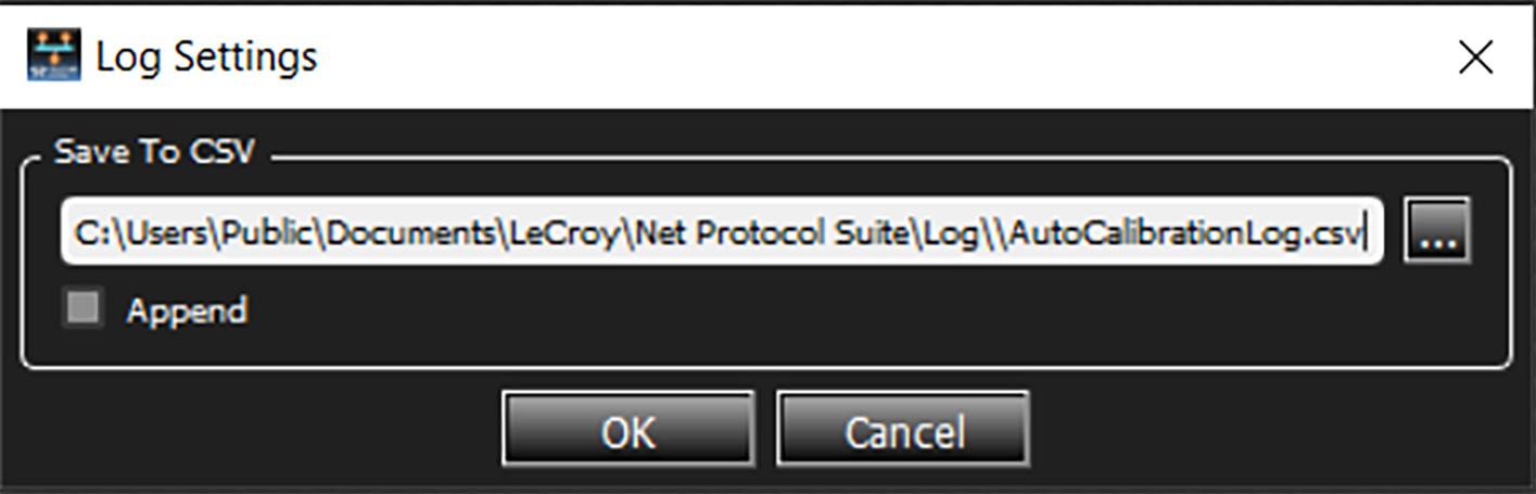
You can change the default path for the log file and append a new file to prevent overwriting the previous file.
-
From the Auto Calibration settings dialog, select the checkbox for Enable Calibration Log, then click the wrench icon

-
To change the default path, enter a new path or click

-
To prevent overwriting the previous file, click the Append checkbox.
Note: When using Append, you can distinguish between new and old data; the software enters a timestamp at the beginning of each new set of data.
-
Once you are satisfied with your changes, click OK. The Link Status window reappears.
-
Click Auto Calibration to start the Auto Calibration.
The following is a snippet from the end of an actual log file. It shows auto-calibration attempting different Presets and reaching status OK when BER is adequate. See M648 Calibration Log Status Codes for an explanation of result codes.
Preset10,_1-5-1-2,SAMPLING,size 13,5e-4
Preset10,_1-5-1-2,SAMPLING,size 14,5e-4
Preset10,_1-5-1-2,UNSTABLE_LINK,BestStableTime 0ms,5e-4
Preset10,_1-5-1-2,UNSTABLE_LINK,BestStableTime 0ms,5e-4
Preset10,_1-5-1-2,UNSTABLE_LINK,BestStableTime 0ms,5e-4
Preset10,_1-5-1-2,UNSTABLE_LINK,BestStableTime 0ms,5e-4
Preset10,_1-5-1-2,UNSTABLE_LINK,BestStableTime 0ms,5e-4
Preset10,_1-5-1-2,UNSTABLE_LINK,BestStableTime 0ms,5e-4
Preset11,_1-6-1-2,SAMPLING,size 1,0e+0
Preset11,_1-6-1-2,SAMPLING,size 2,2e-8
Preset11,_1-6-1-2,SAMPLING,size 3,0e+0
Preset11,_1-6-1-2,SAMPLING,size 4,1e-8
Preset11,_1-6-1-2,SAMPLING,size 5,0e+0
Preset11,_1-6-1-2,SAMPLING,size 6,3e-8
Preset11,_1-6-1-2,SAMPLING,size 7,0e+0
Preset11,_1-6-1-2,SAMPLING,size 8,2e-8
Preset11,_1-6-1-2,SAMPLING,size 9,0e+0
Preset11,_1-6-1-2,SAMPLING,size 10,3e-9
Preset11,_1-6-1-2,SAMPLING,size 11,0e+0
Preset11,_1-6-1-2,SAMPLING,size 12,1e-8
Preset11,_1-6-1-2,SAMPLING,size 13,0e+0
Preset11,_1-6-1-2,SAMPLING,size 14,2e-8
Preset11,_1-6-1-2,OK,,1e-9
Preset11,_1-6-1-2,OK,,3e-8
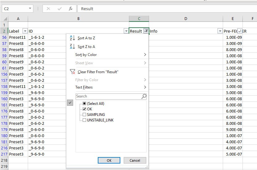
The image below is an example of a log output in Excel. The log is filtered to only show results that were OK and sorted by the Pre-FEC BER. This combination produces the following results:
-
Results = OK for Presets 3, 8, 9, and 11.
-
Preset 11 shows the lowest Pre-FEC BER. Therefore, Preset 11 was chosen as optimal.
M648 Calibration Log Status Codes
|
Result |
Information |
Description |
|
SAMPLING |
Dwell time sampling |
Auto Calibration is still sampling Link Status to meet Dwell time setting. |
|
NO_LINK |
Setting skipped due to no link |
Received Loss of Sync Link Status |
|
UNSTABLE_LINK |
Setting skipped due to unstable link during dwell time |
Link Status is neither Idle nor Frames throughout dwell time, and there are up to x ms time where Status is Linked (Idle or Frame). |
|
BAD_LINK |
Setting skipped due to high error |
Status is linked but there are x Uncorrectable FEC errors detected. |
|
OK |
Setting is added to Candidate list |
Link is stable and Uncorrectable FEC error is 0. |
|
ACCEPT |
Candidate is added to Preset list |
Link is stable, Uncorrectable FEC error is 0, and Pre-FEC BER is below target value. |
Probe Calibration (for SierraNet M408 and SierraNet M168)
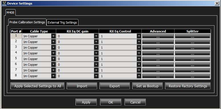
In the Device Settings window, select the Probe Calibration Settings tab. Depending on the project’s protocol configuration, the Device Settings tab appears slightly different.
These settings are meant for advanced users to tune the performance of the Analyzer receiver ports, the Jammer receiver and transmitter ports, and the Analyzer DUT link pass-through path. In most cases, the default settings will perform well and should be used as-is.
40 GigE Configurations
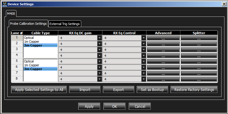
You can manually calibrate the probe settings. Set the parameters for the following:
-
Cable Type: Select Optical, 1m, 2m, 3m, or 5 meter Copper. (See Cables to Use with M408/M168 Analyzer).
-
RX Eq DC gain: Select a value from the drop-down list.
-
RX Eq Control: Select a value from the drop-down list.
-
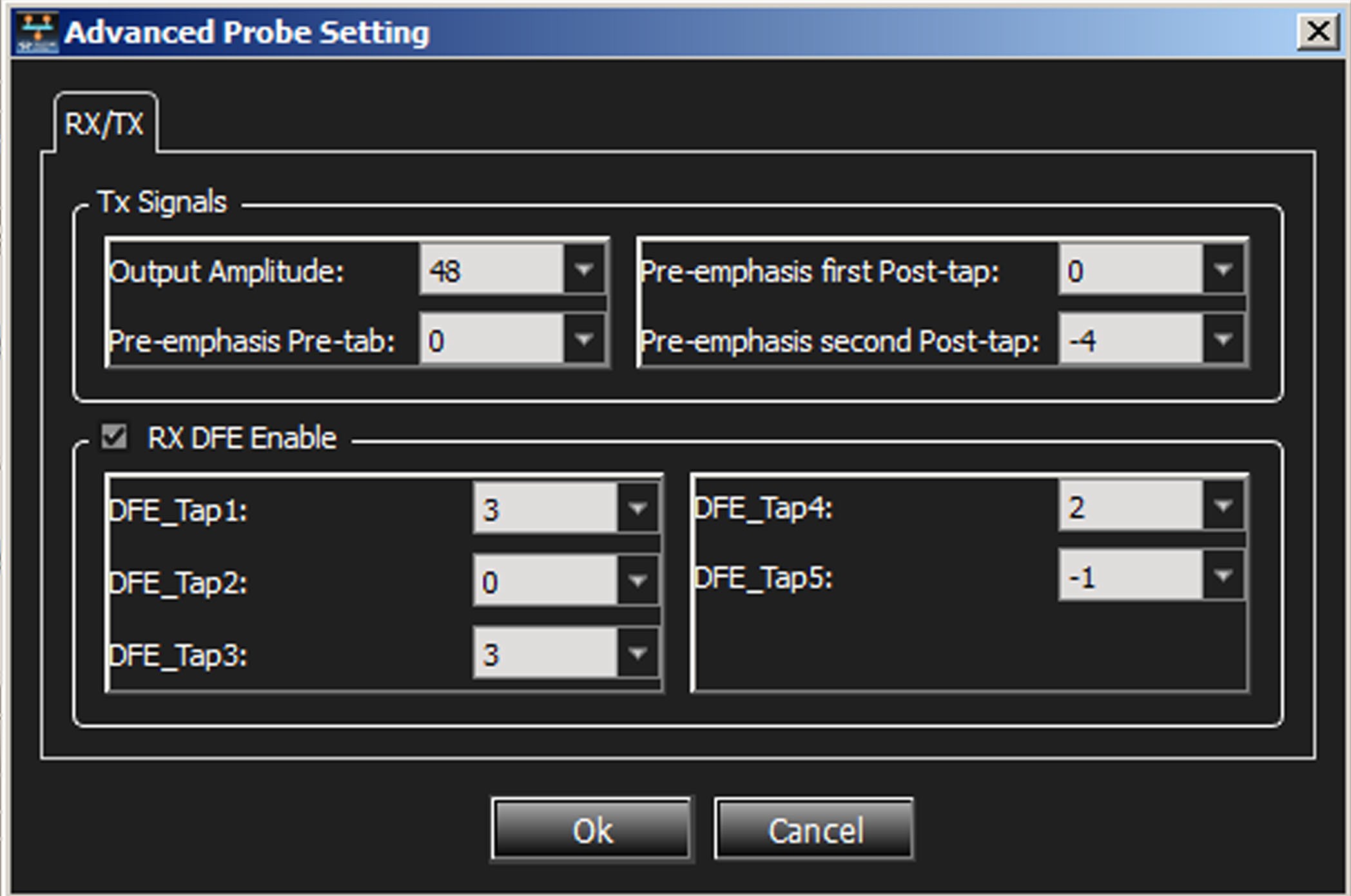
Advanced: Displays the Advanced Probe Setting window. Enter the desired values for each of the parameters.
-
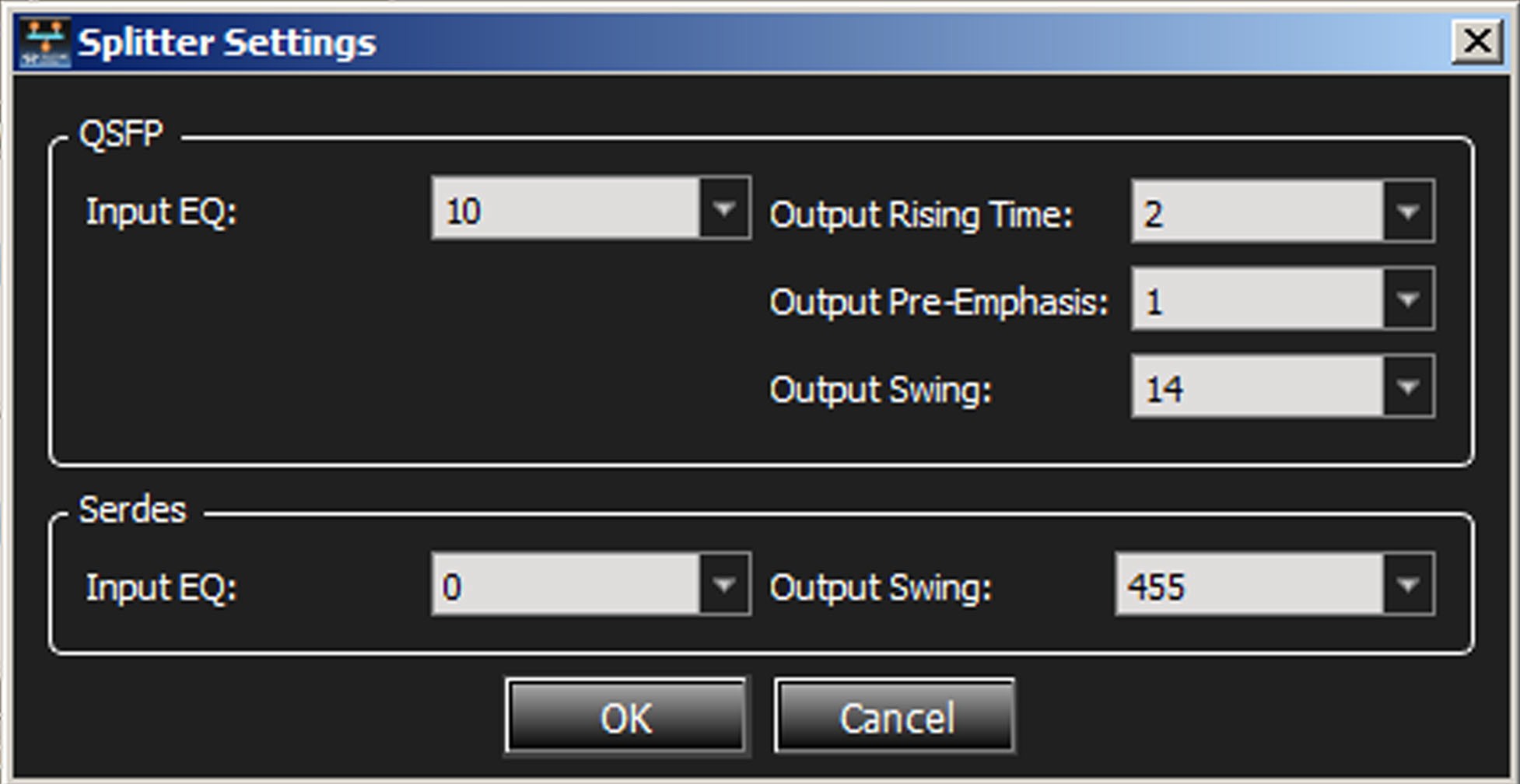
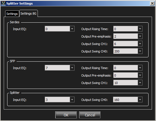
Splitter: Displays the Splitter Settings window.
-
Apply Selected Settings to All: Applies the settings selected in the currently selected port to all ports in the list.
-
Import: Loads calibration settings from *.csv file.
-
Export: Creates a new *.csv file.
-
Set as Bootup: Loads these settings into memory; rebooting will automatically load these values.
-
Restore Factory Settings: Restores factory settings.
10 GigE Configurations
You can manually calibrate the probe settings. To do this, set the parameters for the following:
-
Cable Type: Select 1m, 3m, or 5m Copper. (See Cables to Use with M408/M168 Analyzer).
-
RX Eq DC gain: Select a value from the drop-down list.
-
RX Eq Control: Select a value from the drop-down list.
-
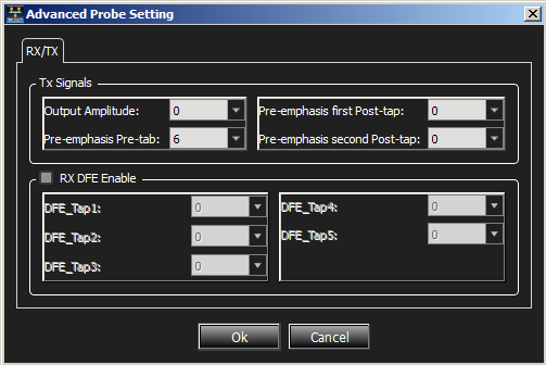
Advanced: Displays the Advanced Probe Setting window. Enter the desired values for each of the parameters.
-
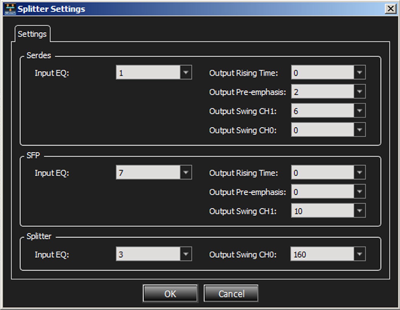
Splitter: Displays the Splitter Settings window.
-
Apply Selected Settings to All: Applies the settings selected in the currently selected port to all ports in the list.
-
Import: Loads calibration settings from *.csv file.
-
Export: Creates a new *.csv file.
-
Set as Bootup: Loads these settings into memory; rebooting will automatically load these values.
-
Restore Factory Settings: Restores factory settings.
FC Configurations
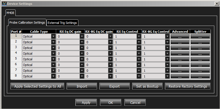
You can manually calibrate the probe settings. Set the parameters for the following:
-
Cable Type
-
RX Eq DC gain: Select value from the drop-down list.
-
RX-8G Eq DC gain: Select value from the drop-down list.
-
RX Eq Control: Select value from the drop-down list.
-
RX-8G Eq Control: Select value from the drop-down list.
-
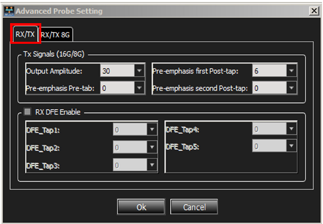
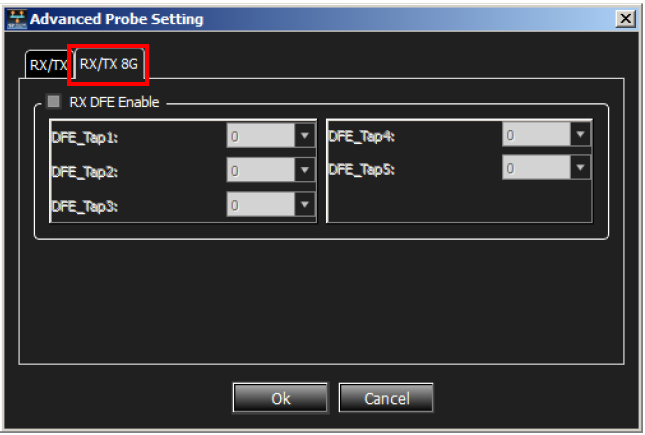
Advanced: Displays the Advanced Probe Setting window with the RX/TX tab selected. Enter the desired values for each of the parameters. Select the RX/TX 8G tab and enter the desired values for each of the parameters.
-
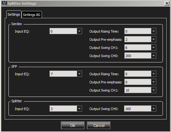
Splitter: Selecting Splitter displays the Splitter Settings window. Enter the desired values for each of the parameters. Select the 8G tab and enter the desired values for each of the parameters.
-
Apply Selected Settings to All: Applies the settings selected in the currently selected port to all ports in the list.
-
Import: Loads calibration settings from *.csv file.
-
Export: Creates a new *.csv file.
-
Set as Bootup: Loads these settings into memory; rebooting will automatically load these values.
-
Restore Factory Settings: Restores factory settings.
External Trigger
External Trigger In and Out connectors appear on the front panel.
-
Use External Trigger In to trigger the analyzer from an external source, such as a scope or other test equipment: Attach the source to the input for External Trigger In, then set up the analyzer to trigger on the External Trigger In signal, as described below.
-
The External Trigger Out can be used to trigger other equipment when the analyzer detects a specified sequence of events on the probed links.
Note: This window applies to all configurations.
-
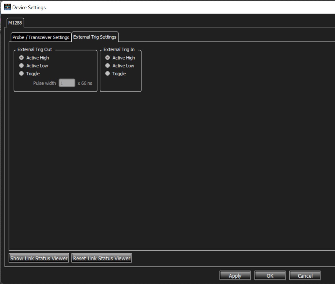
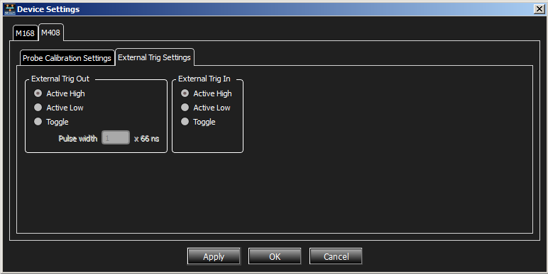
In Device Settings, select the External Trig Settings tab.
This shows the External Trig Out Setting and External Trig In Setting as Active, Active Low, or Toggle (shown below).
External Trig Out
The Analyzer can send a Low or High external signal any time a trigger occurs.
Select the External Trig Out Setting: High Active, Low Active, or Toggle from High to Low or Low to High once (3.3 V output).
Enter the External TrigOut pulse width.
External Trig In
An external Low or High input signal can cause triggering.
Select the External Trig In Setting: Active High, Active Low, or Toggle from High to Low or Low to High once (3.3 V input).
The nominal External Trigger voltage is 0.818 volts. Trigger In can work with 1 volt to 5 volts input voltage.