
You must install the software before connecting the analyzer to the host machine for the first time. For optimal performance, follow standard optical cable cleaning procedures every time a cable is unplugged and replugged into an optical module.
Connecting the SierraNet M1288 Analyzer
Note: Connect to and from devices using cables suitable for your setup. The M1288 supports single and multi-mode fiber, active copper, and passive copper cabling. See Introduction.
-
Connect the Ethernet cable between the SierraNet M1288 Analyzer Ethernet Port and one of the following:
-
Ethernet Port on the host machine
-
Ethernet switch
-
Gigabit Ethernet interface
-
You can also connect a USB cable from the USB port on the analyzer to the host machine.
-
Connect the analyzer to a 100V–240V, 50Hz–60Hz power outlet and turn on the Power switch. The host machine detects the analyzer, loads the driver files, then the analyzer undergoes the initialization as shown on the LCD display.
-
Connect your devices under test using either optical modules and fiber cables or appropriate copper cabling, suitable for your configuration.
-
Connect your devices under test to port pairs P1-P2, P3-P4, or P5-P8. See M1288 Connections.
M1288 Connections
The SierraNet M1288 has 3 sets of connectors: P1-P2, P3-P4 and P5-P8. Each set has different characteristics and different capabilities.
Ports P1-P2
These ports are digitally re-timed, and are often called “the Jammer ports”, though they can also act as analyzer ports. These ports use QSFP-DD cages, but only lanes 0 through 3 are connected. Traffic going to P1 is digitally re-timed in the M1288 and sent back out on P2, and vice-versa. As only 4 lanes are connected, these ports can be used to analyze, Jam or exercise GbE traffic up to 400Gbps on a single SierraNet M1288 unit.
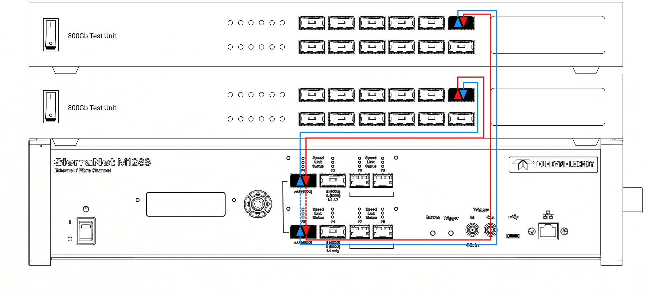
The benefit of using ports P1-P2 is that it is not necessary to use a M1288 Probe.
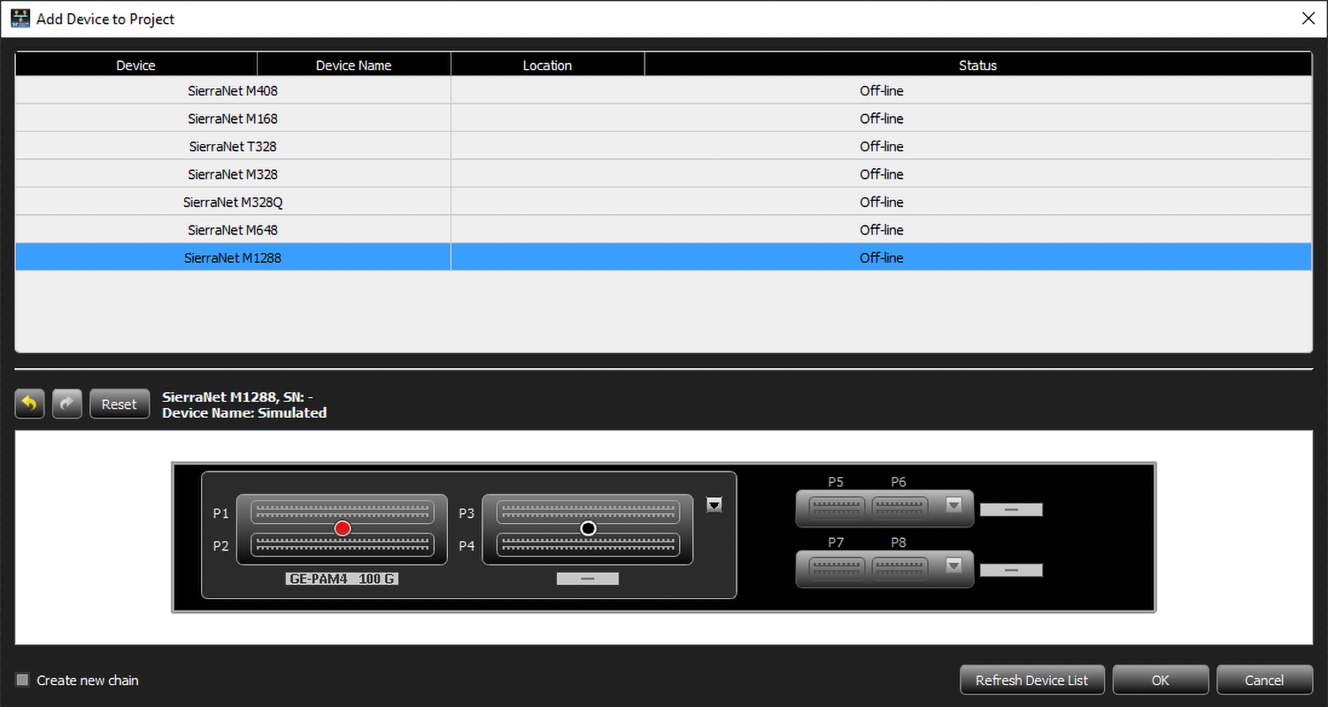
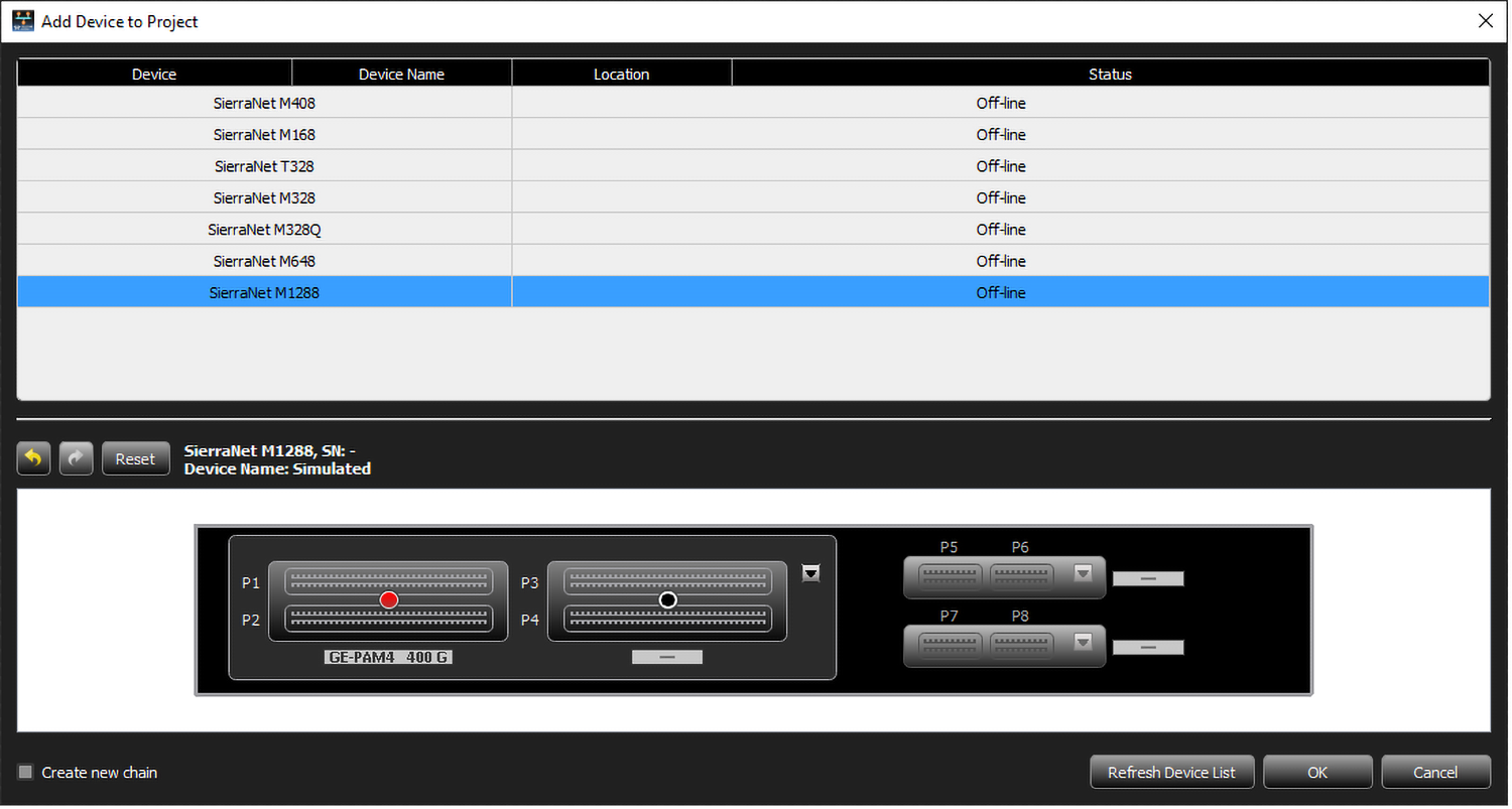
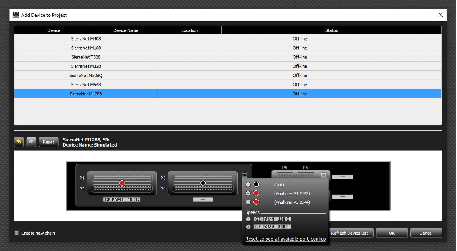
In the Sierra Net Protocol Suite software, the port configuration options for P1-P2 connections are shown in the figures below.
Ports P3-P4
These ports are purely analyzer ports, they only analyze the input traffic on them, and do not copy it over between them. Using these ports requires the use of the M1288 Probe unit (sold separately). The M1288 Probe is used to 'close the loop' between the 2 DUTs by connecting traffic between the DUT ports and sending a copy to the P3-P4 ports. These ports use QSFP-DD cages, and all 8 lanes (0-7) are connected, allowing for up to 800Gbps traffic analysis:
-
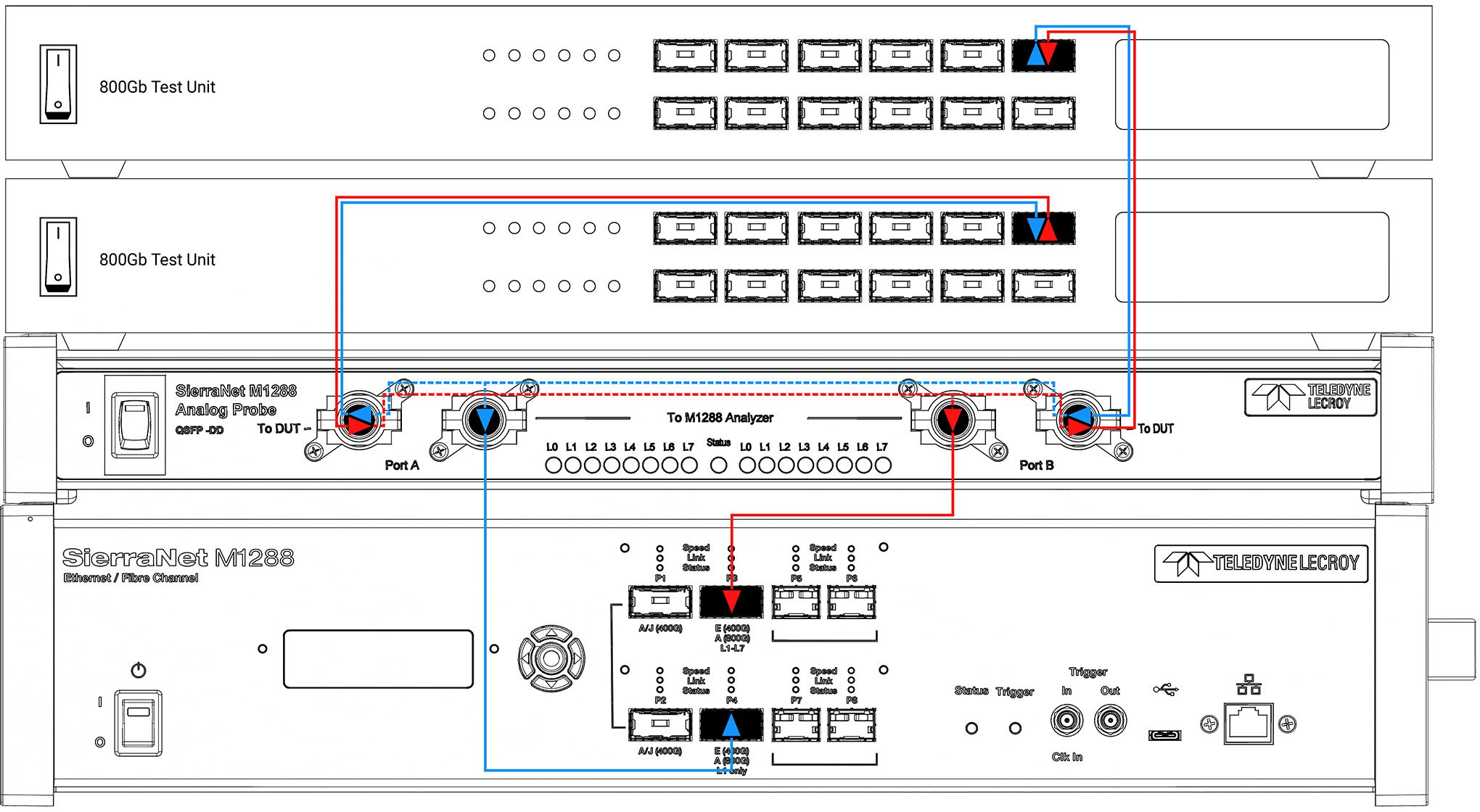
For both L1 and full stack (L1 through L7) analysis in 800GbE (only Auto Negotiation (AN) and Link Training (LT)), these ports can be used on a single SierraNet M1288 unit and the M1288 Probe, as shown below.
-
Once connected, the central Status light on the M1288 Analog probe will display the connection status:
-
RED: Both analyzer QSFP cables are not connected
-
BLUE: One analyzer QSFP cable is connected
-
Green, blinking: Both analyzer QSFP cables are connected
-
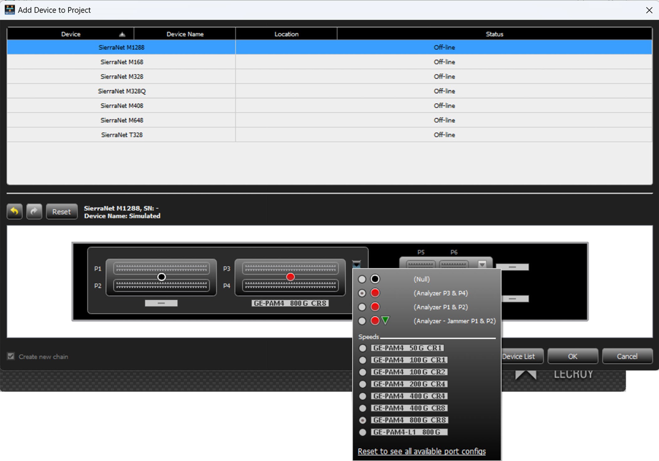
In the Sierra Net Protocol Suite software, the port configuration options for P3-P4 connections are shown below.
Ports 5-8
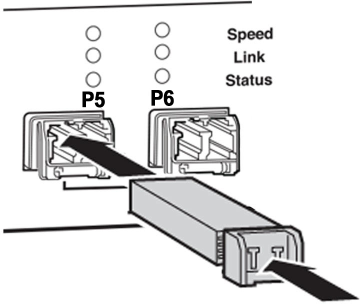
These SFP112 ports are digitally retimed and used for 128GFC. Connect to and from devices using multi-mode optical modules and cables suitable for your setup. P5 / P6 are used as a pair for one link, and P7 / P8 are used as a pair for a different link. Refer to the release notes for a list of supported optical modules.
You may optionally use a Multimode LC Optical TAP inline rather than having the analyzer be inline. Connect the Multimode LC Optical TAP to these ports to capture and analyze short-range optical links that use an SFP interface. The Optical TAP can be used to test NICs, HBAs, or Switches that use compatible SFP interfaces.
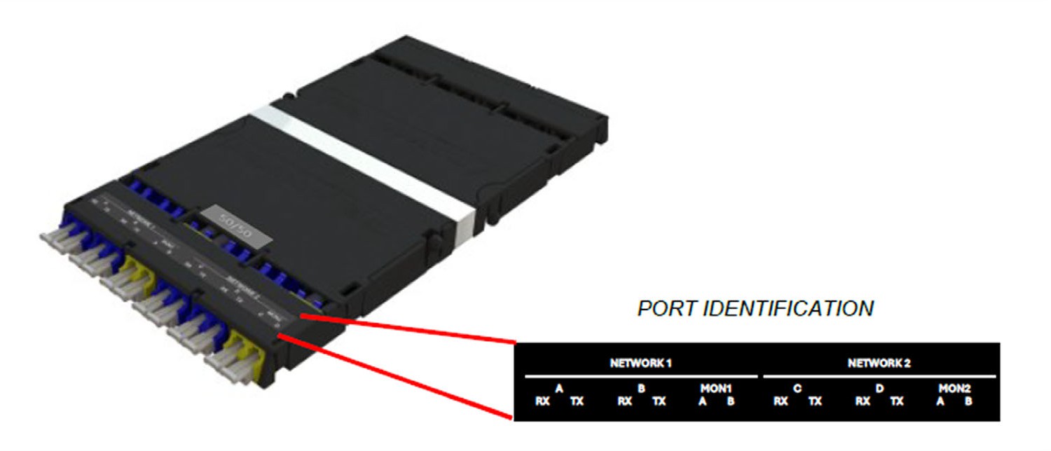
The Optical TAP connects to the link under test via the Network 1 A/B LC connectors; transmissions from these ports are passively reflected out the Mon1 A/B LC port, which is connected to the SierraNet analyzer for recording. A second link can be simultaneously tapped via the Network 2 ports.
The TAP ports are set up as follows:
Network 1 A and B: Devices under test connect to these ports via LC fiber cables. These ports are cross-connected internally so that the connected devices will link with each other.
Mon1: This port connects to the SierraNet analyzer via an LC fiber cable for monitoring the A/B link.
Network 2 C and D: Used for a second link.
Mon2: Used for a second link.
Connecting the TAP and Making a Recording
LC fiber cables and optical transceivers are not included with the TAP. Refer to the Net Protocol Suite readme file for a list of SFP optical transceivers that are supported in the SierraNet analyzer.
Device A and Device B link through the TAP's Network 1 A/B ports. Device A transmissions are reflected out the Mon1 A port. Device B transmissions are reflected out the Mon1 B port.
Follow these instructions to connect the analyzer to the Optical TAP:
-
On the TAP, connect the LC duplex cable connector to Mon1.
-
On the SierraNet analyzer, use the Rx sides of both ports of a configured port pair (P5/6 or P7/8) to connect. Split apart the LC duplex cable connector into two simplex connectors; plug one simplex connector into the Rx side of one analyzer port and the other simplex connector into the Rx side of the other analyzer port.
When you’ve connected the analyzer to the Optical TAP, you’re ready to make a recording:
-
In Net Protocol Suite, create new project for the analyzer.
-
Choose the port pair the Mon1 port of the TAP is connected to, and select a compatible analyzer configuration.
-
With certain analyzers and configurations, you might need to set the link speed in the Recording Settings to a specific speed (not Auto).
-
Start recording.
Connecting the SierraNet M648 Analyzer
-
Connect the Ethernet cable between the SierraNet M648 Analyzer Ethernet Port and one of the following:
-
Ethernet Port on the host machine
-
Ethernet switch
-
Gigabit Ethernet interface
-
You can also connect a USB cable from the USB port on the analyzer to the host machine.
-
Connect the analyzer to a 100V–240V, 50Hz–60Hz power outlet and turn on the Power switch.
Once the analyzer is turned on, the host machine detects the analyzer, loads the driver files, then the analyzer undergoes the initialization as shown on the LCD display.
-
Connect your devices under test using either optical modules and fiber cables or appropriate copper cabling, suitable for your configuration.
-
Connect your devices under test to port pairs P1/P2, P3/P4, P5/P6, P7/P8 and/or P9/ P10, shown below.
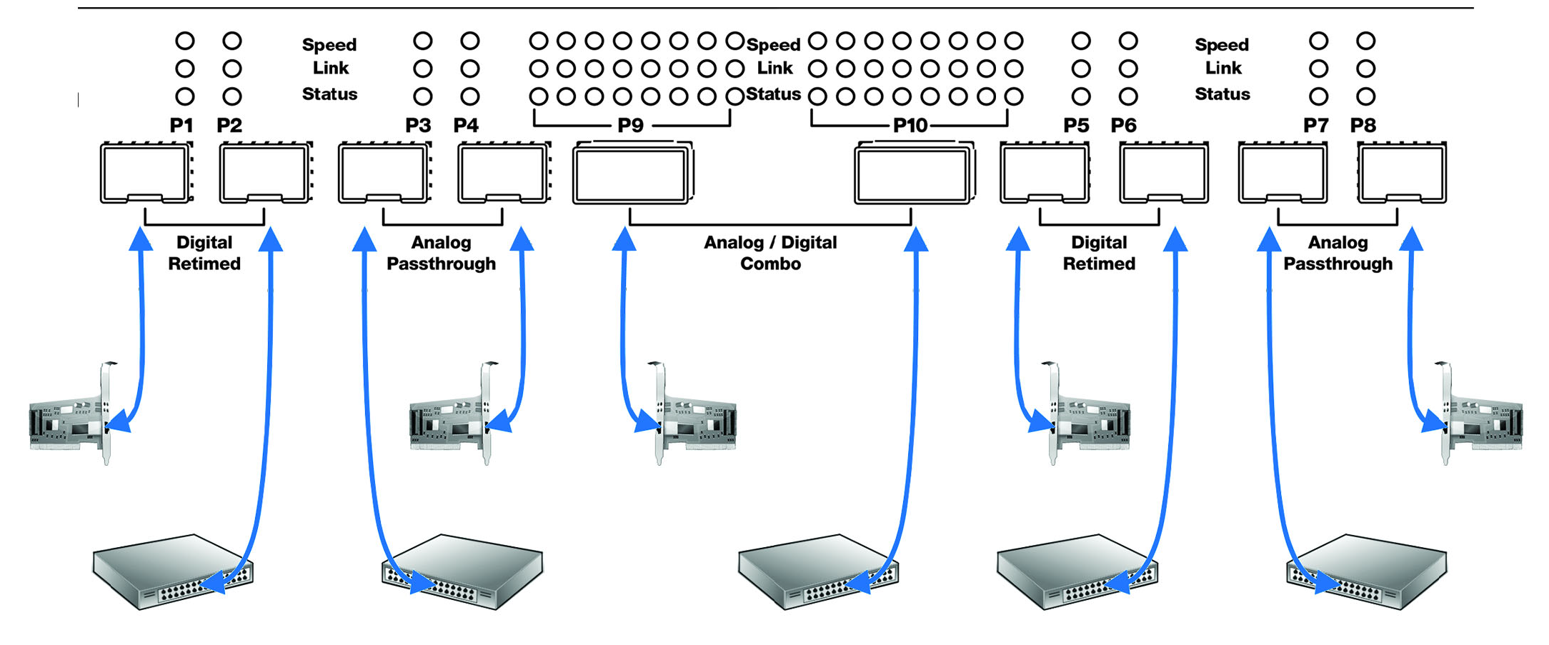
Cables to Use with the M648 Analyzer
Connect to and from devices using optical modules and cables suitable for your setup. Single and multi-mode fiber, active copper, and passive copper cabling is supported.
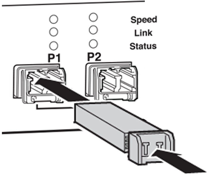
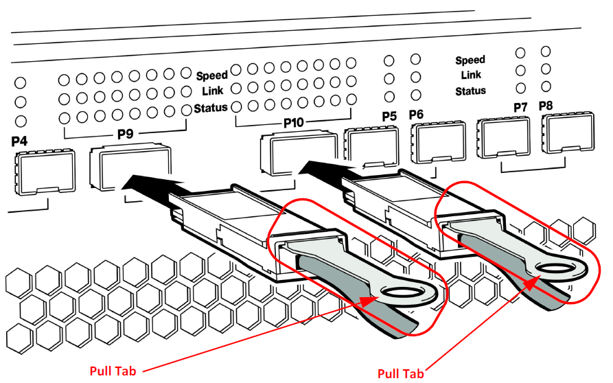
400G L1 Analysis

400G L1 Analysis is unique in that:
-
There is no L2 and up support.
-
400G L1 port configuration only records the Auto Negotiation (AN) and Link Training (LT) phases of the link bring-up. Full speed data cannot be recorded; this includes any L2 or higher traffic, but also the full PRBS phases of the link bring-up. This affects the Link LED, which works in reverse; that is, during Link bring-up, the LED will be lit, but once the link is up, the Link LED will go dark.
-
PRBS can only be recorded on one lane.
-
Unpacked mode and the requirement to select the specific lane for showing PRBS.
-
You cannot record actual 400G traffic; you can only record the sections of the link bring up such as Speed Negotiation (SN) and Link Training (LT).
M648 Dual User Support
The Sierra M648 now supports two users to simultaneously connect to a single unit, with both working independently on a different set of SFP ports.
This is easier to explain by defining “Hemispheres”, as follows:
-
Hemisphere 1: P1-P4
-
Hemisphere 2: P5-P8
Each Hemisphere can be connected individually by a different user. A single user can still connect to both Hemispheres at once by reverting to the standard mode of operation.
Note: The QSFP-DD ports CANNOT be split/shared.
When Dual User mode needs to be used, you can either open the new project from the menu or by activating a unit on another project.
Note: To allow Dual User support, you must make sure the following TCP ports are open on your network firewall: 5000 to 5003; 6000 to 6003.
Ask your IT department to add the above ports to your firewall exceptions.
Creating a New Project for Dual User Support
Follow these steps to create a new project (if needed) for either hemisphere:
-
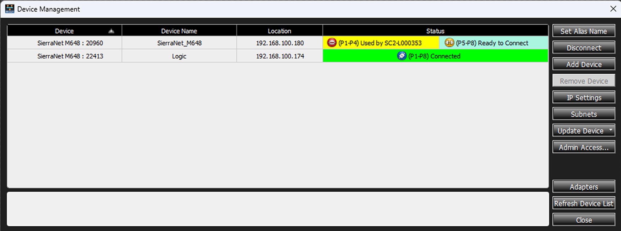
Connect to the unit from the Device Management window. As shown below, the unit will show that it is connected to both hemispheres if they are available. However, it will update later, when the new project is created.
-
Go to File > New Project to create a new project. The Add Device to Project dialog opens. Select any port configuration in the first or the second hemisphere.
Note: If you choose port configuration in both hemispheres, the unit will remain in full mode and cannot be used by other users.
When you check the Device Management window after creating a project, it will show that only one of the hemispheres is connected. If you check the Device Management window from another machine, it will show that only one hemisphere is available.
Activating a Unit on an Existing Project for Dual User Support
Alternately, you can activate a unit on an existing project. To do this, right-click on the device and select a unit from the drop-down list as shown below.
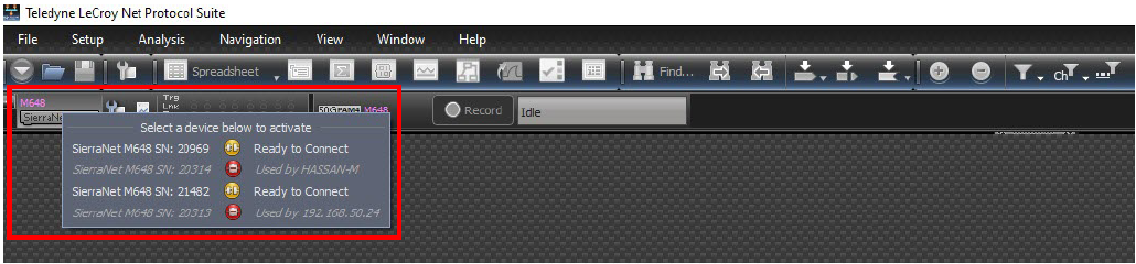
In the dual user mode, the above option is available to activate the unit, which follows the rules shown in the table below.
Dual User Mode Rules
|
Port Configuration in Project |
Visible Units |
|---|---|
|
0-A-0-A A-0-A-0 AJ-0-AJ-0 AJ-0-0-A AE-0-AE-0 |
Only units with all ports available will be listed in the menu. |
|
0-A-0-0 A-0-0-0 AJ-0-0-0 AE-0-0-0 |
Only units with all ports available, and units with P1-P4 available will be listed in the menu. If all ports of a unit are available, then it will be listed as two items in the menu. This means that in this case you have two options, one is to activate all ports on the project, and the second is to activate only P1-P4 on the current project. |
|
0-0-0-A |
Only units with all ports available, and units with P5-P8 available will be listed in the menu. If all ports of a unit are available, then it will be listed as two items in the menu. This means that in this case you have two options, one is to activate all ports on the project, and the second is to activate only P5-P8 on the current project. |
The following limitations apply:
-
Global/shared resources, like external trigger in/out and cascading, may not function as expected if both users try to use them. For example:
-
If two users connect to the unit at the same time, and if User 1 sets the External Trigger Out and User 2 also does the same thing, then the output signal may not be what both users expect.
-
Also, if user 1 sets the External Trigger in the Jammer/Exerciser, and User 2 has an External Trigger In in their project, then the analyzer will be triggered. So any shared hardware resource can be used only by one user.
-
Cascading (in general) and CrossSync (specifically) are not supported in Dual User mode.
-
-
In Device Management, when a user connects to half of the unit, there are the following limitations:
-
Device update is disabled. It means the user can only update the device when connected to all ports.
-
IP settings is functional (enabled) only if the user is connected to all ports.
-
Connecting the SierraNet T328 Analyzer
-
Connect the Ethernet cable between the SierraNet T328 Analyzer Ethernet Port and one of the following:
-
Ethernet Port on the host machine
-
Ethernet switch
-
Gigabit Ethernet interface
-
You can also connect a USB cable from the USB port on the analyzer to the host machine.
-
Connect the analyzer to a 100V–240V, 50Hz–60Hz power outlet and turn on the Power switch.
Once the analyzer is turned on, the host machine detects the analyzer, loads the driver files, then the analyzer undergoes the initialization as shown on the LCD display.
-
Connect your devices under test using either optical modules and fiber cables, or appropriate copper cabling suitable for your configuration.
-
Connect your devices under test to port pairs P1/P2, P3/P4, P5/P6 and/or P7/P8.
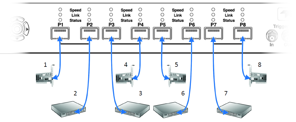
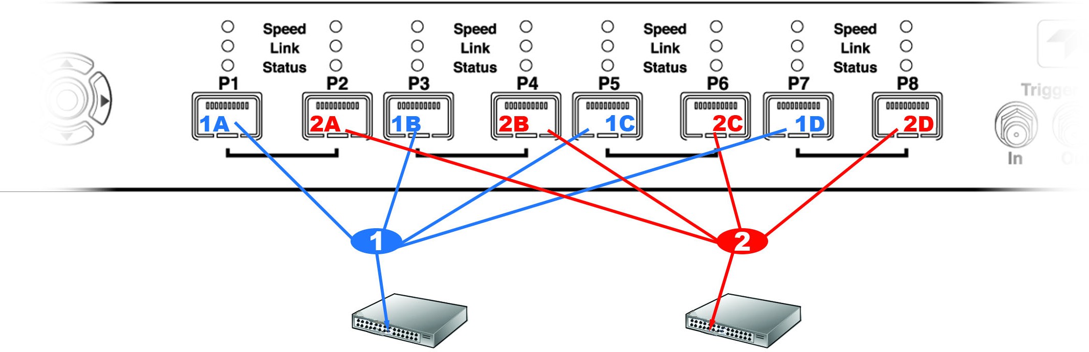
For 100GbE configurations where the link under test ports are QSFP, a pair of QSFP-4xSFP breakout cables is required to connect the T328 to the link under test.
-
For cable 1, connect the QSFP end to the port at one end of the link under test, and connect the SFP ends to the analyzer; i.e., 1A->P1, 1B->P3, 1C->P5, and 1D->P7.
-
For cable 2, connect the QSFP end to the port at the other end of the link under test, and connect the SFP ends to the analyzer; i.e., 2A->P2, 2B->P4, 2C->P6, and 2D->P8 of the analyzer.
Cables to Use with T328 Analyzer
Connect to and from devices using optical modules and cables suitable for your setup. Single and multi-mode fiber, active copper, and passive copper cabling are supported.
Connecting the SierraNet M328Q Analyzer
-
Connect the Ethernet cable between the SierraNet M328Q Analyzer Ethernet Port and one of the following:
-
Ethernet Port on the host machine
-
Ethernet switch
-
Gigabit Ethernet interface
-
You can also connect a USB cable from the USB port on the analyzer to the host machine.
-
Connect the analyzer to a 100V–240V, 50Hz–60Hz, power outlet and turn on the Power switch.
Once the analyzer is turned on, the host machine detects the analyzer, loads the driver files, then the analyzer undergoes the initialization as shown on the LCD display.
-
Connect the devices under test using either optical modules and fiber cables or appropriate copper cabling, suitable for the configuration.
-
Connect the devices under test to port pairs P1/P2, P3/P4, P5/P6 and/or P7/P8.
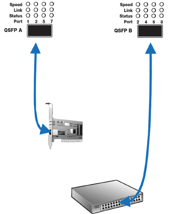
Cables to Use with M328Q Analyzer
Connect to and from devices using optical modules and cables suitable for your setup. Single and multi-mode fiber, active copper, and passive copper cabling is supported.
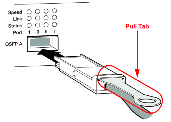
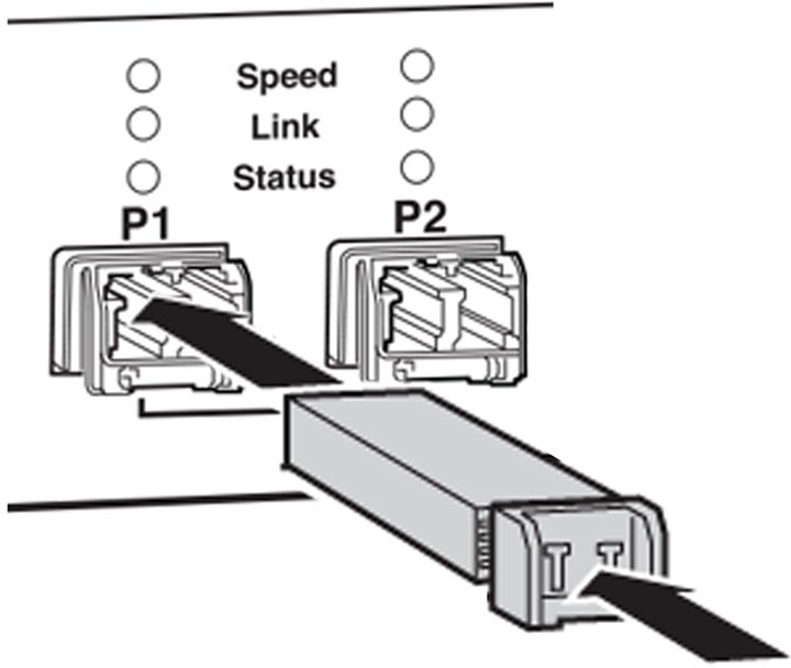
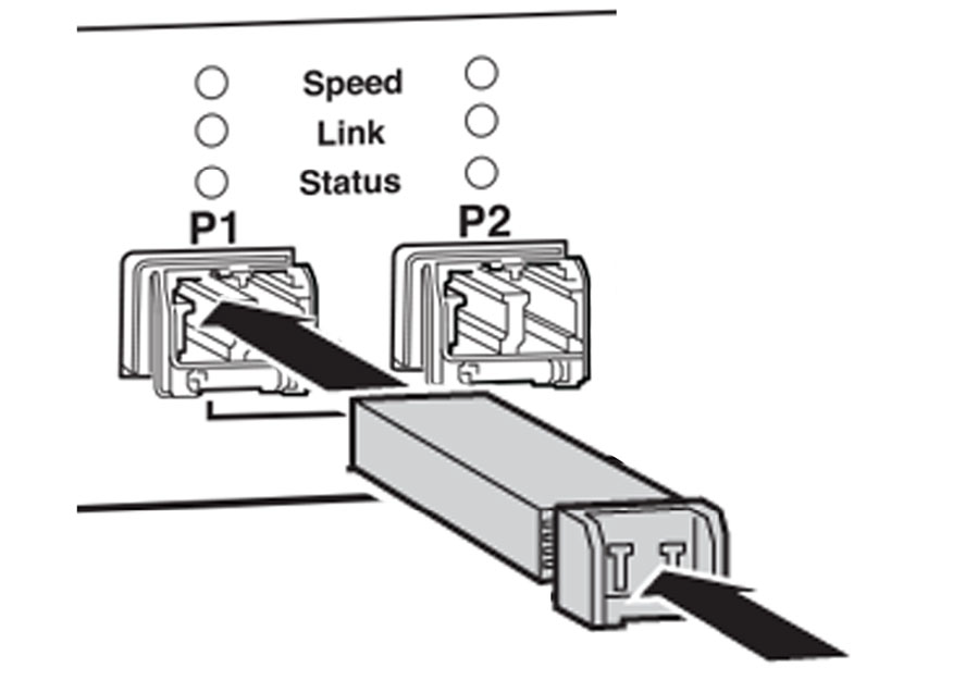
Note: Use the plastic pull tab to disconnect the cable from the analyzer.
Analysis Configuration
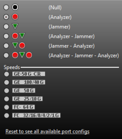
For analysis only, the supported port configurations are shown below:
Analysis and Jamming
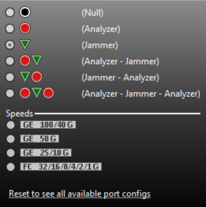
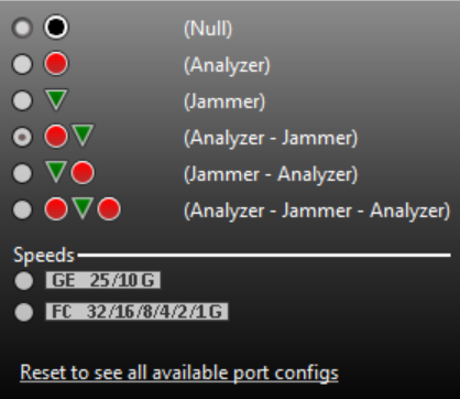
For analysis and jamming, the supported port configurations are shown below:
|
|
|---|
-
P1/P2 ports are used for connecting a DUT link. Before Jammer traffic can be assigned to P1/P2 in the trace and After Jammer traffic will be assigned to P3/P4 in the trace. The physical P3/P4 ports on the unit are not used, though their LEDs will reflect the After Jammer link state.
-
P5/P6 ports are used for connecting another DUT link. Before Jammer traffic will be assigned to P5/P6 in the trace, and After Jammer traffic will be assigned to P7/P8 in the trace. The physical P7/P8 ports on the unit are not used, though their LEDs will reflect the After Jammer link state.
Connecting the SierraNet M328 Analyzer
-
Connect the Ethernet cable between the SierraNet M328 Analyzer and one of the following:
-
Ethernet Port on the host machine
-
Ethernet switch
-
Gigabit Ethernet interface
-
You can also connect a USB cable from the USB port on the analyzer to the host machine.
-
Connect the analyzer to a 100V–240V, 50Hz–60Hz, power outlet and turn on the Power switch.
Once the analyzer is turned on, the host machine detects the analyzer, loads the driver files, then the analyzer undergoes the initialization as shown on the LCD display.
-
Connect your devices under test using either optical modules and fiber cables or appropriate copper cabling, suitable for your configuration.
-
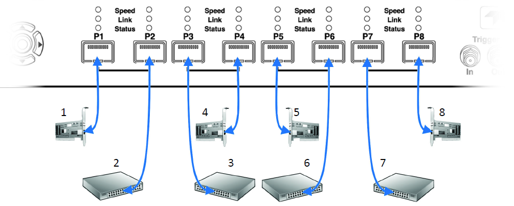
Connect your devices under test to port pairs P1/P2, P3/P4, P5/P6 and/or P7/P8. See below.
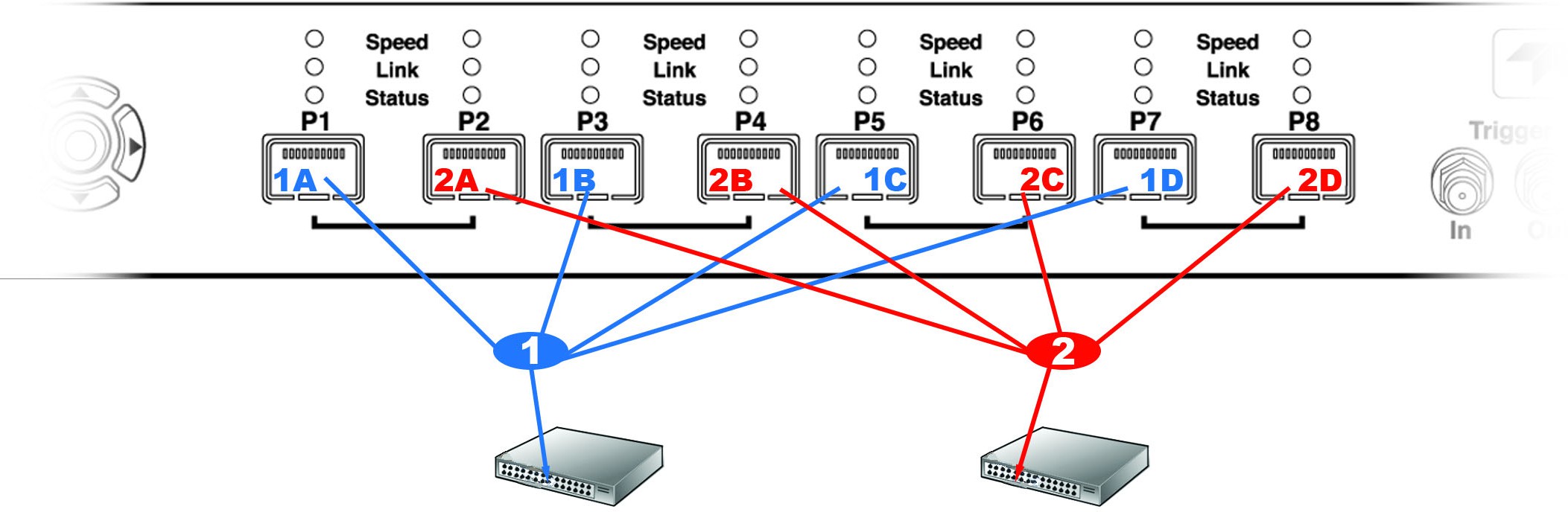
For 100GbE configurations where the link under test ports are QSFP, a pair of QSFP-4xSFP breakout cables is required to connect the T328 to the link under test.
-
For cable 1, connect the QSFP end to the port at one end of the link under test, and connect the SFP ends to the analyzer; i.e., 1A->P1, 1B->P3, 1C->P5, and 1D->P7.
-
For cable 2, connect the QSFP end to the port at the other end of the link under test, and connect the SFP ends to the analyzer; i.e., 2A->P2, 2B->P4, 2C->P6, and 2D->P8 of the analyzer.
Cables to Use with M328 Analyzer
Connect to and from devices using optical modules and cables suitable for your setup. Single and multi-mode fiber, active copper, and passive copper cabling is supported.
Analysis Configuration
For analysis only, the supported port configurations are shown below:
Analysis and Jamming
For analysis + jamming the supported jammer port configurations are shown below:
|
|
|
|---|
-
P1/P2 ports are used for connecting a DUT link. Before Jammer traffic can be assigned to P1/P2 in the trace and After Jammer traffic will be assigned to P3/P4 in the trace. The physical P3/P4 ports on the unit are not used, though their LEDs will reflect the After Jammer link state.
-
P5/P6 ports are used for connecting another DUT link. Before Jammer traffic will be assigned to P5/P6 in the trace, and After Jammer traffic will be assigned to P7/P8 in the trace. The physical P7/P8 ports on the unit are not used, though their LEDs will reflect the After Jammer link state.
Connecting the SierraNet M408/M168 Analyzer
To set up the analyzer:
-
Connect the analyzer to a 100V–240V, 50Hz–60Hz power outlet and turn on the Power switch.At power on, the analyzer will go through initialization as shown on the LCD display.
-
Connect the USB cable between the SierraNet M408/M168 USB port and a USB port on the Host PC. The host PC operating system detects the analyzer and configures the drivers automatically. (See 2.5.2, Connecting via Ethernet for Ethernet connectivity.)
-
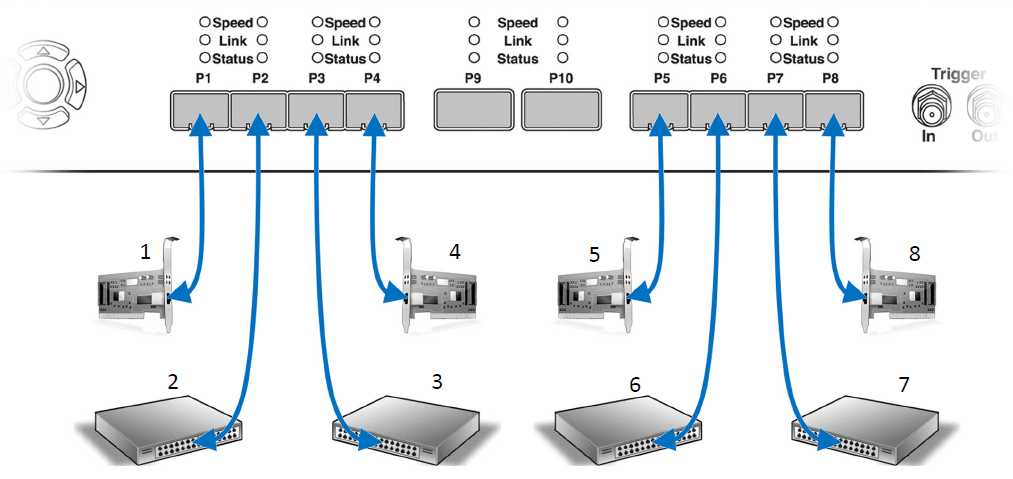
Connect the analyzer as shown in the following figure, which shows connections between Port-pairs P1-P2 to Device 1 and Device 2; P3-P4 to Device 3 and Device 4; and so on.
-
Bi-Directional data traffic flows through the analyzer to/from Device 1 through Port 1 and to/from Device 2 through Port 2. Bi-Directional data traffic flows similarly between Devices/Ports 3 & 4, 5 & 6 and 7 & 8.
-
M408 only — For QSFP connections, Bi-Directional data traffic flows through the analyzer to/from Device 9 through Port 9, and to/from Device 10 through Port 10.
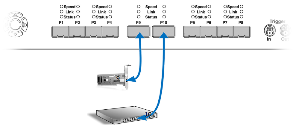
Note: The P9/P10 ports are only available on the SierraNet M408.
Cables to Use with M408/M168 Analyzer
Connect to and from devices using SFP+/QSFP and a cable suitable for your setup. Single and multi-mode fiber, active copper, and passive copper cabling is supported.
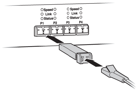
For passive copper Ethernet cabling, the M408/M168 has been calibrated to work optimally with the following cables:
-
40 GigE cables (M408 only) Molex 74757-1101 (1 meter, 30 awg QSFP)
-
10 GigE cables: Molex 74752-2101 (1 meter 28 awg SFP)