
The Link Status Viewer allows you see if your link is up and if so the health of the link. The two most important things shown are described below.
Note: This section only applies to the SierraNet M648 and SierraNet M1288 models and only to PAM4 port configurations.
Overview of PAM4 Link Signaling
50G PAM4 Ethernet (50GE) signaling is done with two logical lanes transmitted over one physical lane. Each logical lane has a unique marker value transmitted on it. The physical media can be electrical backplane, twinaxial copper or fiber.
64G PAM4 Fibre Channel (64GFC) is done with one logical lane over one physical lane and only has one alignment marker as opposed to two markers for 50GE. The physical media is typically optical fiber.
In order for a 50GE link to come up, the physical coding sublayer must first achieve alignment marker lock (AM lock) on both logical lanes. After marker lock on all lanes is achieved the logical lanes are deskewed and reordered.
For 64GFC the M648 protocol analyzer physical coding sublayer splits the incoming signal into two bit streams and individually locks onto the two halves of the single 64GFC alignment marker.
Lock to only half of the markers may indicate that Gray coding, polarity or other settings are not consistent.
After the logical lanes are locked, deskewed and reordered, the bit error rate (BER) of the logical lanes and of the entire link can be found by counting the bit errors in correctable FEC blocks.
An RS(544,514) FEC block is a 5440-bit block of link data. This 5440-bit block consists of 544 10-bit symbols. An RS(544,514) FEC can correct up to 15 symbols in a single 544 symbol FEC block.
Using the Link Status Viewer
To open the Link Status Viewer:
-
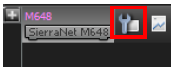
Click the wrench icon to the right of the device. The Device Settings window opens.
-
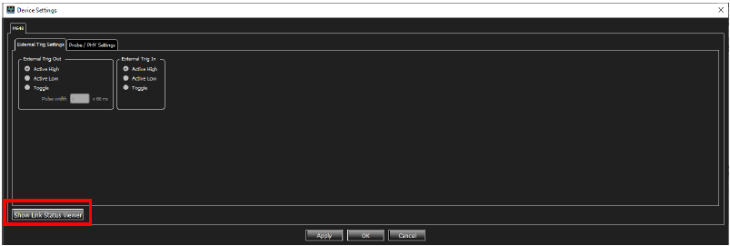
Click Show Link Status Viewer. Examples of Link Status Pane displays are shown below.
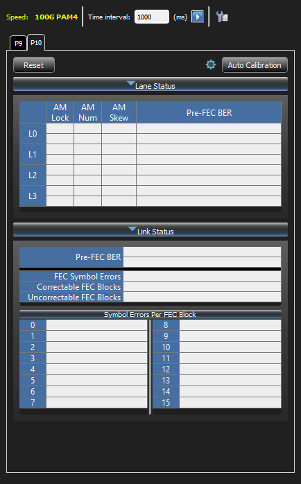
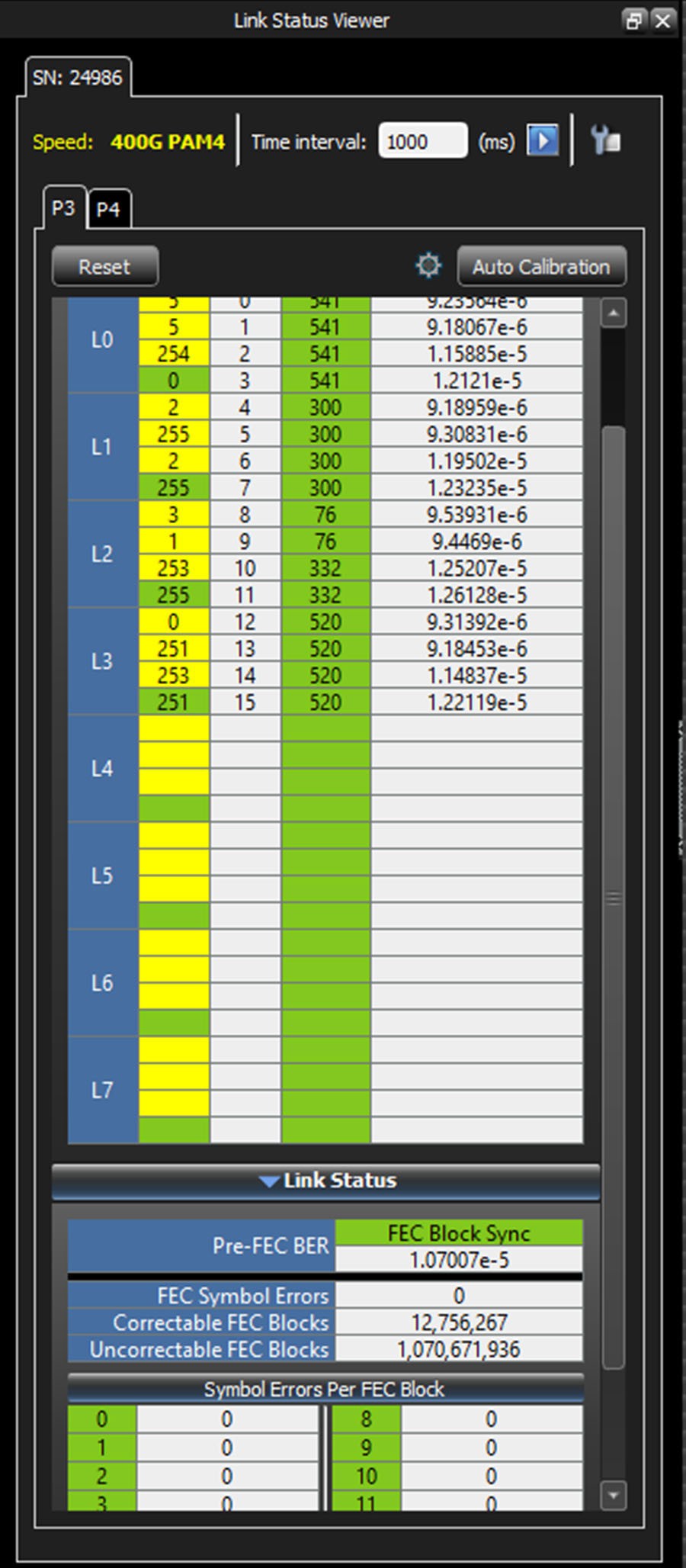
The Link Status Viewer contains the following information:
Lane Status
-
AM Lock (Alignment Marker Lock)
-
A healthy link shows the AM Lock column green for both marker lockers 0 and 1.
-
If either marker lock 0 or 1 bounces out of lock and then relocks the color for that AM lock is yellow.
-
If either marker lock 0 or 1 is currently unlocked the color for that AM Lock is red.
-
-
AM Num (Alignment Marker Number)
-
Each logical lane has a unique marker value. The marker value found is shown.
-
No color for AM Num.
-
-
AM Skew (Alignment Marker Skew)
-
The logical lanes may be skewed in time. The AM Skew column indicates the number of bits the logical lanes are skewed relative to each other.
-
The 50GE spec (802.3cd) maximum skew spec is 4781 bits.
-
-
Lane Status Pre-FEC BER (pre-FEC bit error rate)
-
The number of bits errors are counted for each logical lane and the bit error rate (BER) is shown.
-
At 50GE each logical lane is 26.5625 Gbps. Five bit errors on one logical lane in one second would result in a lane BER of 1.88e-10
-
If marker lock is not achieved this value is blank.
-
Link Status
-
FEC Block Sync
-
If the FEC decoder receives three consecutive FEC blocks that have no errors or are correctable then FEC block sync is achieved and the field is highlighted green.
-
If FEC block sync is lost and regained the field is highlighted yellow.
-
If the FEC decoder receives three consecutive FEC blocks that are uncorrectable then FEC block sync is lost and the field is highlighted red.
-
-
Link Status Pre-FEC BER (pre-FEC bit error rate)
-
The number of bits errors are counted for all logical lanes and the bit error rate (BER ) is shown.
-
At 50GE the link is 53.125 Gbps. A total of twelve bit errors across all logical lanes in one second would result in a link BER of 2.26e-10.
-
No color.
-
-
FEC Symbol Errors
-
The total number of symbol errors counted since counter reset.
-
Uncorrectable FEC blocks 16 of this count since the number of symbol errors is unknown in this case.
-
No color.
-
-
Correctable FEC Blocks
-
The total number of correctable FEC blocks counted since counter reset
-
No color
-
-
Uncorrectable FEC Blocks
-
The total number of uncorrectable FEC blocks counted since counter reset.
-
If zero and FEC block sync, the field is highlighted green.
-
If non-zero and FEC block sync, the field is highlighted orange.
-
-
Symbol Errors per FEC Block
-
This is a bucket counter of symbol errors per FEC block. The number of symbol errors in a correctable RS(544,514) FEC block is known and can range from 0 to 15 symbol errors. For example if a correctable FEC block with three symbols errors occurs then Symbol Errors Per FEC Block[3] would increment by 1.
-
These symbol error counters are an indicator of the link health. Symbol errors per FEC block [0-9] are always highlighted green.
-
If symbol errors per FEC block [10-15] are non-zero this indicates a link with a high BER and is likely to have uncorrectable FEC blocks. Non-zero values are highlighted yellow.
-
Link and Lane Status per Port
Both Link and Lane status are available per port.
Time Interval
Time interval for reading all the above information can be selected.
Reset
The content of counters per port can be reset.
Probe/Phy Settings
-
Open Link Status and probe settings in real-time to see how any change in probe/ phy settings impacts link status.
-
There are two tab pages for ports, and each tab page shows the link status for one port.
-
The time interval timer value is 1000ms by default. The minimum allowed value is 200ms.
-
-
To change the interval, open link status view and change the value, then press the Start icon next to the time interval timer. The session restarts with the new value.
There are two expandable sections in the view (Lane Status and Link Status). Both sections can be expanded or collapsed.