
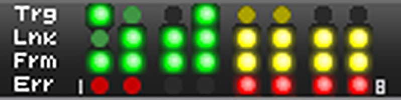
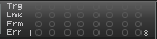
The Port Status pane displays the status of the link on each port: Trigger, Link, Frame, or Error.
|
Trigger LEDs |
Frm LEDs |
||
|
Null |
|
Null |
|
|
Green |
|
Green |
|
|
Link LEDs |
Err LEDs |
||
|
Null |
|
Null |
|
|
Red |
|
Red |
|
|
Colored |
Link establishment; decoding LED color coding matches HW Link LED. |
|
|


Dashboard of Per-Port Status
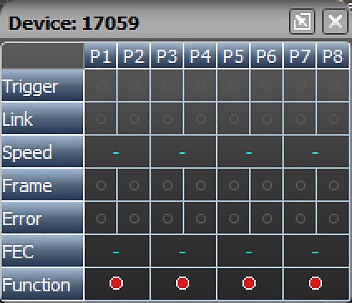
If you roll your cursor over the Port Status panel, additional information appears. You will see the serial number of the product as well as the Status of the following functions per port:
-
Trigger
-
Link
-
Speed
-
Frame
-
Error
-
Forward Error Correction (FEC)
-
Function
Right-click in the Port Status Pane to open a menu. Select one of the four following options:
-
Reset resets the LED history.
-
Real Time Statistics opens the Real Time Statistics window (see 4.4.1, Real Time Statistics).
-
SFP Information opens information about the “Small Form-Factor Pluggable” connection (see Small Form-Factor Pluggable (SFP) Connection) and the Rx and Tx Power Levels per Port (see Tx/Rx Power Tab).
-
Show Link Status Viewer displays the Link Status of the connected ports.
Small Form-Factor Pluggable (SFP) Connection
When you select SFP Information, the following window appears.
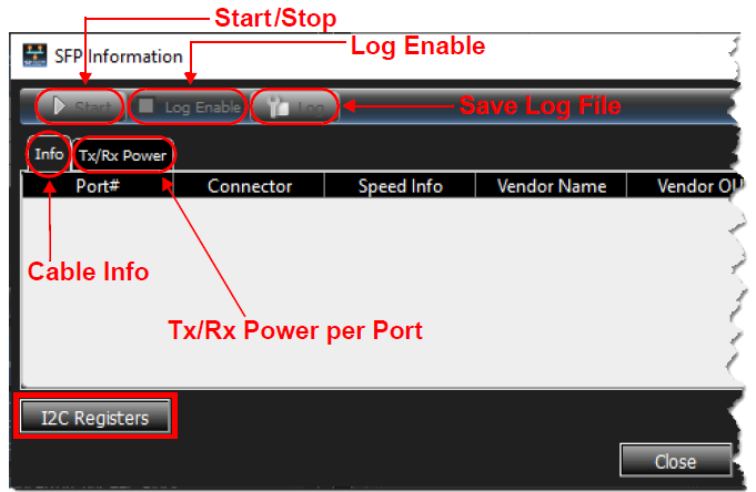
When connected to a unit with cables plugged in, you can click the Start button to Read the information from the cables.
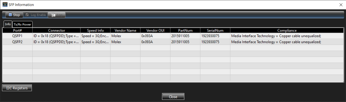
To view the cable information, select the Info tab and Start:
-
Port #
-
Connector
-
Vendor Name
-
Vendor OUI
-
PartNum
-
SerialNum
-
Compliance
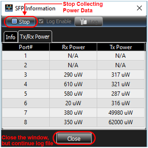
To view the Tx and Rx power per port, select the Tx/Rx Power tab and Start.
Tx/Rx Power Tab
There are three functions in the window:
-
Port #
-
Rx Power
-
Tx Power
The image below shows six active ports.
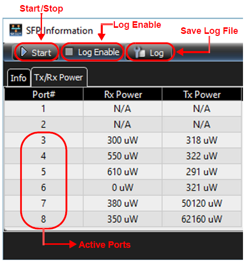
-
To set up a Log file to keep a record of the power readings, check Log Enable and click Start.
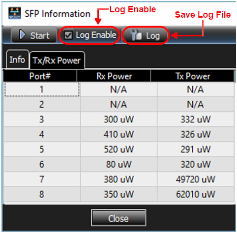
-
To save your log file, select the Log tab

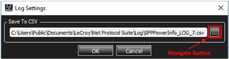
-
Click the Navigate button

-
Enter a meaningful file name, then click Save.
-
Once you have created the log file, return to the original Rx/Tx Power window and click Start.
-
With the Log Enabled, the power readings are saved.
-

-
The data is stored in comma separated value (CSV) format. An example log file is shown below.
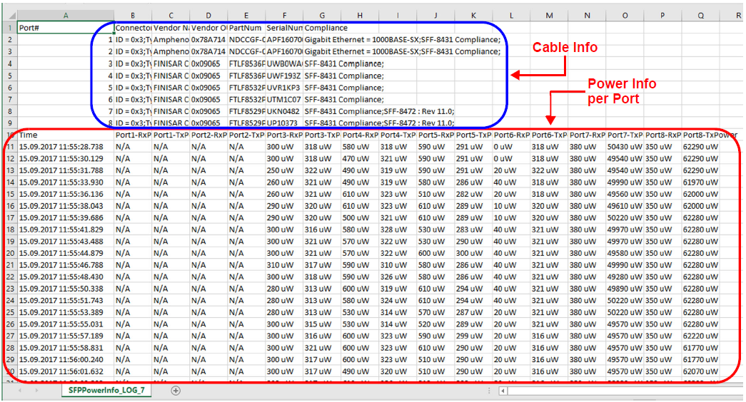
This example shows the time each reading was taken and the active ports, as well as the cables attached to the analyzer.
-
Power readings were taken about every 1.5 seconds and will continue until you Stop the logging.
-
Click Close to close the window. The power data remains logged until you reopen the Tx/Rx Power and click the Stop button.
I2C Write/Read Registers
This feature allows you to manually Add, Edit, and Delete I2C Registers. When new I2C settings get programmed manually for specific modules (whether Optic or DAC), the software logs these and automatically programs them the next time the same module (i.e., same part number) is detected, so that the link comes up automatically.
To create a new I2C Register, do the following:
-
From the main screen, right-click on the Port Status area
-
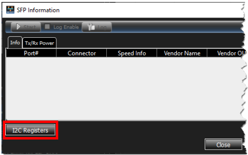
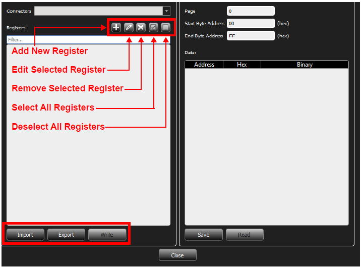
Click the I2C button at the bottom left corner of the SFP Information window. The Transceiver Modules I2C Write/Read dialog window opens.
-
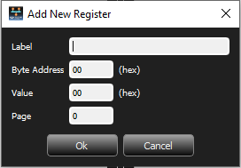
Click Add

-
Enter a Label, Byte Address, Value, and Page for the New Register.
-
Repeat steps 1 through 4 as needed.
-
When you are satisfied with your entries, click OK.
You can click Cancel at any time to close the New Register dialog box and return to the Write/Read dialog window.
Note: When different modules are used, the unit must be deactivated and reactivated so that the changes will be detected and the proper settings applied.
-
If you need to delete a Register, highlight it and click the Delete button.
-
To modify a Register, do the following:
-
Highlight the Register you need to modify and click Edit Selected Register.
-
Make the necessary corrections in the Edit Register dialog box and click OK.
-
-
To Export a Register, do the following:
-
Highlight a Register and click Export. The Export Connector Registers dialog opens.
-
Enter a path and file name in the File name field, then click Save. The register is saved as a JSON file.
-
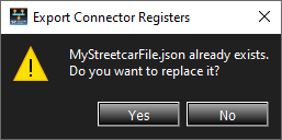
To overwrite an existing file, highlight it and click Save. A confirmation prompt appears. If you are sure you want to overwrite the file, click Yes.
-
Write a Register to the Transceiver Modules
To Write to the Transceiver Modules, click the Write button at the bottom of the left pane.
Note: Write writes the values, one by one, for checked Registers.
Read any Register or range from the Transceiver Modules
To Read any Register or range:
-
From the Transceiver Modules in the right pane, enter the Page, Start Byte Address, and End Byte Address.
-
Click the Read button at the bottom of the right pane.
Note: You can also click Save to save the read results to a file.