The Trace View comprises the following features:
-
Packet view display uses color and graphics to document captured traffic.
-
Selected packets, transactions, and so on, are highlighted with a blue background and black border (see image below). The selected packet is synchronized among views. Views which show data from a single packet, transaction, etc. (Data View, Detail View, Spec View) will show the contents of this Selected Packet.

-
To move packet selection up or down, click Shift-Up-Arrow or Shift-Down- Arrow.
-
Packets are on separate rows, with individual fields both labeled and color- coded.
-
Packets are numbered (sequentially, as recorded), time-stamped (with a resolution of 8 ns), and highlighted to show the transmitted speed (low-speed, full-speed, or high-speed).
-
Display formats can be named and saved for later use.
-
Pop-up Tool Tips detail the contents of packet fields.
-
Data fields can collapse to occupy minimal space in the display, and you can zoom in and out to optimize screen use.
-
The display software can operate independently of the hardware and so can function as a stand-alone Trace Viewer that may be freely distributed.
-
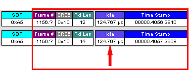
High Speed SOFs display Microframes, shown below.
Anchor Points—Synchronized Views
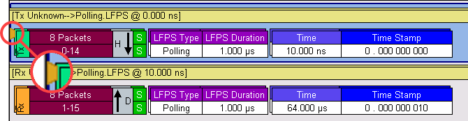
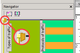
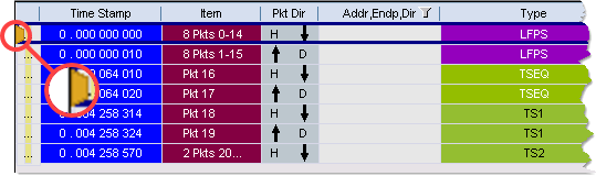
Anchors are provided to indicate the synchronization points between views when scrolling.
These are indicated by a gold trapezoid 
The position within the views are different according to the type of view window. The Anchor is normally the first packet on the screen in the CATC Trace views and Spreadsheet Views.
Refer to the following three images.
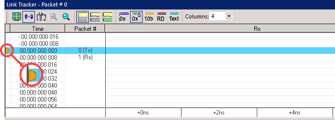
In the Link Tracker view, it is normally on the third row of the display (see the following image).
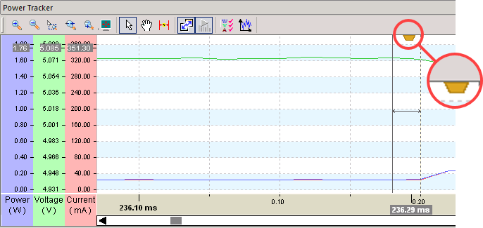
On time-based views, (Link State Timing View, Power Tracker View, Bus Utilization View, etc.), it is normally in the center. Refer to the anchor point in the Power Tracker View in the figure below.
The anchor point can be independent of the current selected item; however, you can move the selected item to the anchor point by double-clicking on it.
USB 3.2 Packets
USB 3.2 has the following packet types:
-
Link Training Sequences
-
TSeq
-
TS1
-
TS1A
-
TS1B
-
TS2
-
-
LFPS Packets
-
Electrical Idles
-
Link Commands
-
SKP
-
Header Packets
-
Payload Packets
-
Data packets
-
Logical Idle Packets
-
BRST
-
BERC
-
BCNT
-
Termination Packets (Time stamped when termination is detected by analyzer)
-
CP
-
VBUS Change (On/Off)
-
SYNC
-
SDS
NOTE: Term On and Term Off are not applicable to M310P/M310e analyzer connectors.
In addition, there are two packet types provided which show symbol traffic which cannot be assembled into a known USB 3.2 packet types:
IPS (Inter-Packet Symbols): These can occur when the link is in U0 but there are symbols seen which do not form a packet. This can be caused by a bad USB cable or some other signal integrity issue. Since these cannot be decoded, this is considered to be an “Error”.
USS (Unidentified Symbol Sequence): These often occur during the transition into and out of U0. Since they are found during this transition period and normally do not interfere with the link coming up or going down, they are classified as a “Warning”. They can generally be ignored.
USB4 Packets—Assigning Protocols using HopID
Since USB4 Packets can contain tunneled protocols, this mapping of HopID to Protocol type can be done manually by doing the following:
Find a tunneled packet you wish to map to a protocol.

Right click on the HopID Field of the Tunneled Packet. Choose one of the Protocol types from the drop-down list.

That HopID will now use the decoder type selected wherever that Hop ID occurs in the same direction.
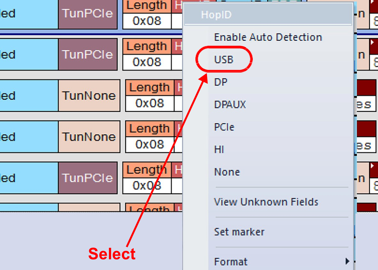
Do the same for the other direction, since HopID values are qualified by the direction.
Hiding/Showing HopID Packets
Click Hide Packets icon 

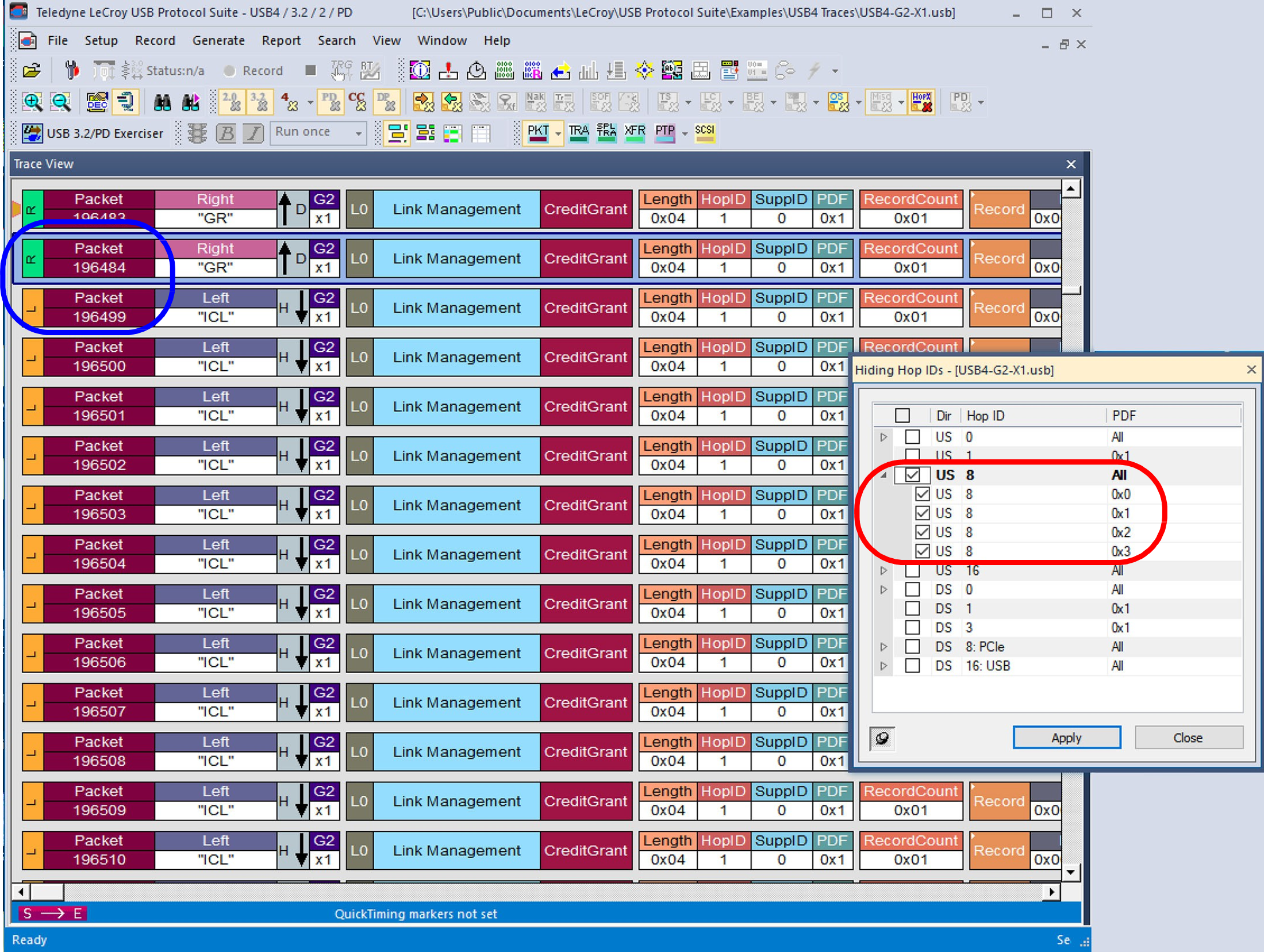
The next two images show the effect of clicking on the HopID Hiding icon.
The first figure has several instances of upstream (US) HopID of 8 from Packet 196485 to Packet 196496.
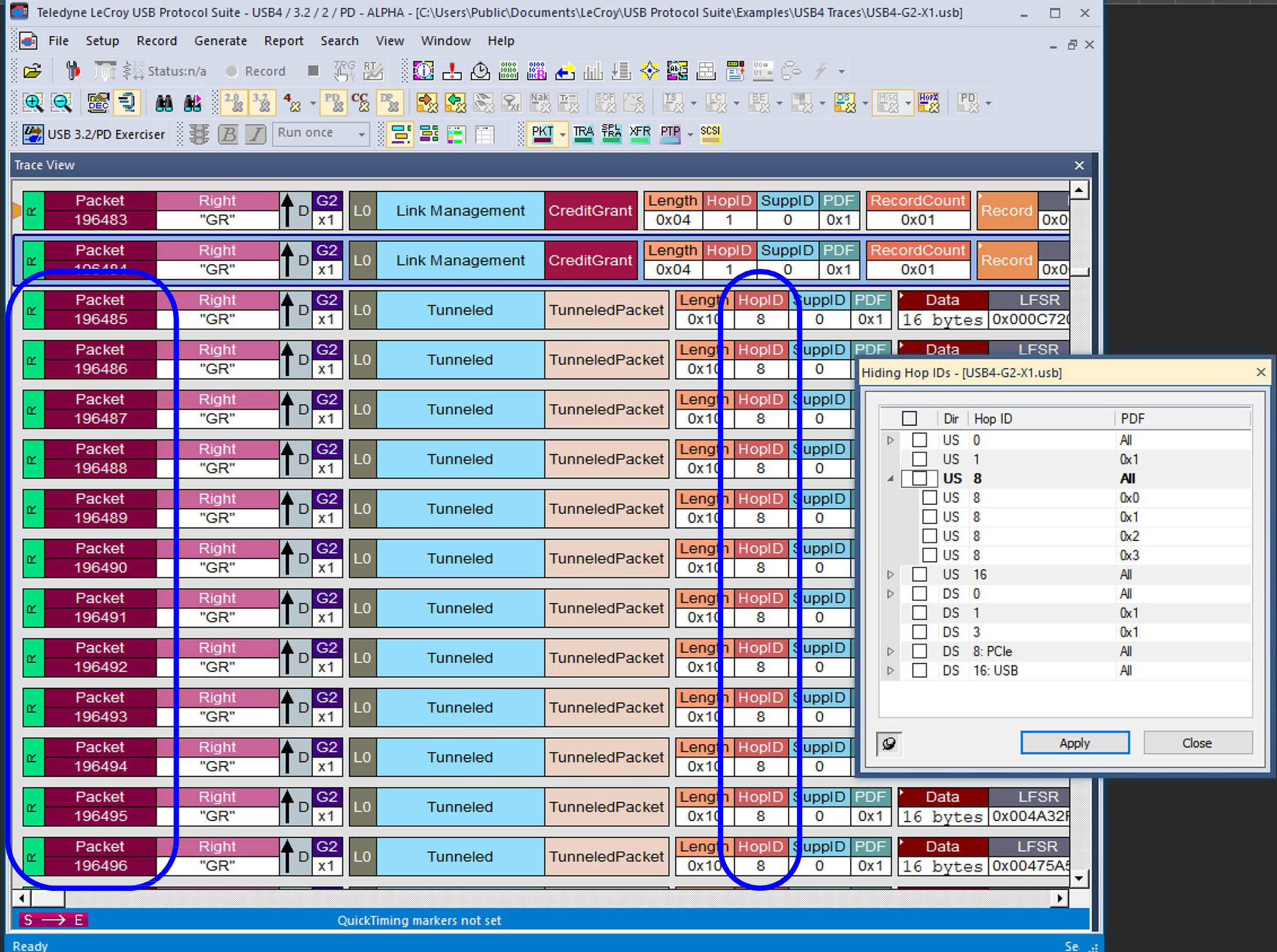
If you want to hide those HopID Packets, select them in the drop-down box and click Apply. Packets from 196485 through 196498 are hidden.
License Info Packets
If the analyzer detects traffic that is not covered by the current license, the recording stops
and a final Info packet is added to the end of the trace describing which capability is not
licensed. The packet includes a Show License Information link that opens the License
Information dialog (see Licenses and Registration).
NOTE: This can occur even when a recording option is set to Auto, since Auto does not
prevent the Host and Device from negotiating traffic that isn't covered by the current license.
Packet Direction
The Packet Direction field displays the direction the packet or signal was traveling on the bus: Downstream from a Host 

In most cases, direction can be determined unambiguously. However, some signals and situations, including protocol errors, cannot be determined with high confidence, since either the Host or Device might be responsible for them. Such cases are marked as Question Marks 
Rather than misidentifying the signal, the software requires you to determine direction (or note an error condition, which is rare). In most cases, you can assume the direction based on the sequence of events that occurred.
Power Delivery Packet Direction
Power Delivery Packets occur on a multi-drop connection. For the Consumers and Providers of Power Delivery, the direction is indicated by the Sink and Source directions cell, and the message is indicated as an SOP type.
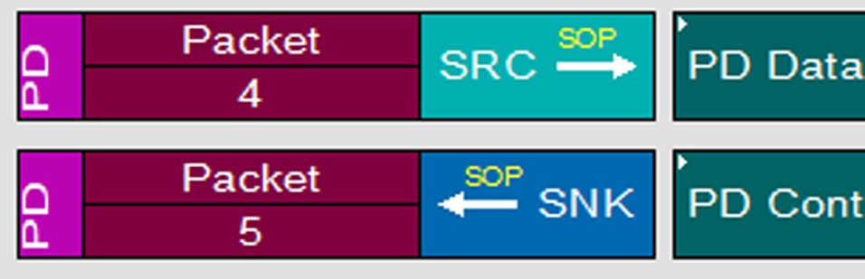
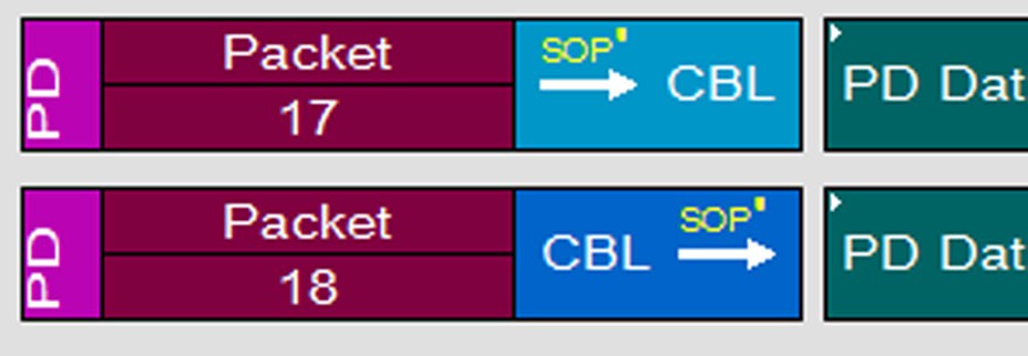
For Cable packets, the indicator is that the source or destination is an SOP' or SOP'' source or destination, as shown below.