
Basic Patterns
Connect/Disconnect
-
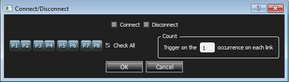
Double-click Connect/Disconnect to open the Connect/Disconnect dialog box.
-
Select Connect/Disconnect and the count of the expected number of occurrences.
-
Select the Check All box to select ports P1 through P8 or individually select ports.
-
Click OK.
Ordered Set
-
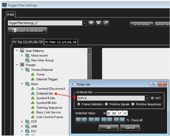
From the Trigger Filter Settings window, double-click Ordered Set. This opens the Order Set dialog box.
-
Select the values for the Ordered Set from the drop-down list. Select Frame Delimiters, Primitive Signals and Primitive Sequences as applicable. Check the Check All box to select ports P1 through P8 or individually select ports.
Symbol 8 Bits
Double-click Symbol 8 bits to open the Symbol 8G Pattern dialog box.
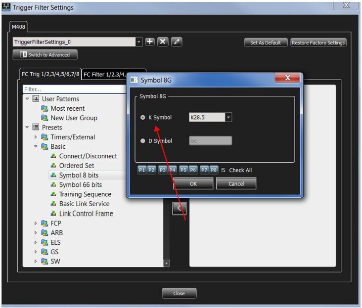
Check K Symbol or D Symbol, as applicable. Select the value for K Symbol from the drop-down list or enter the value for D Symbol. Check the Check All box to select ports P1 through P8 or individually select ports.
Symbol 66 Bits
Double-click Symbol 66 bits to open the Symbol 66 Bits Pattern dialog box.
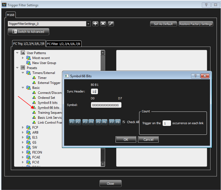
Enter the values for the Sync Header, Symbol and the count of the expected number of occurrences. Check the Check All box to select ports P1 through P8 or individually select ports.
Two different order sets can exist in one 64 bits payload of a 66 bits block. The six examples of a remote and local fault given below demonstrate how to manually enter ordered set triggers.
-
0x0100000001000055 > local fault-local fault
-
0x000000000100004b > local fault-idle
-
0x010000000000002D > idle-local fault
-
0x0200000002000055 > remote fault-remote fault
-
0x000000000200004b > remote fault-idle
-
0x020000000000002D > idle-remote fault
Basic Link Service
Double-click Basic Link Service to open the Basic Link Service Pattern dialog box.
For any FC pattern, double-click the pattern name, for example, double-click Basic Link Service to open the Basic Link Service Pattern dialog box.
Note: Some screen captures for the FC patterns are similar to the screen capture shown below.
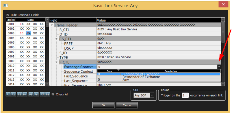
Enter the values for the Frame Header, CS_CTL, F_CTL and the count of the expected number of occurrences. Check the Check All box to select ports P1 through P8 or individually select ports. You can specify the type of SOF to match on for the frame by selecting it from the SOF drop-down list.
Note: Some patterns have additional options to select from drop-drown lists as shown in the figure above.
Link Control Frame
Double-click Link Control Frame in the Pattern window to open the Add Link Control Frame Pattern dialog box.
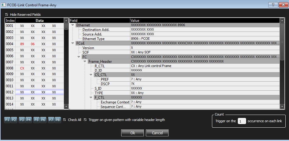
Enter the values for the Frame Header, CS_CTL, F_CTL and the count of the expected number of occurrences. Check the Check All box to select ports P1 through P4 or individually select ports. You can specify the type of SOF to match on for the frame by selecting it from the SOF drop-down list.
The following additional FC patterns are available:
Other FC Patterns
The same pattern types listed for FCoE are also available for native FC as well. Refer to FCoE Patterns above.
FC Protocol Errors
Double-click Protocol Errors to open the dialog box.
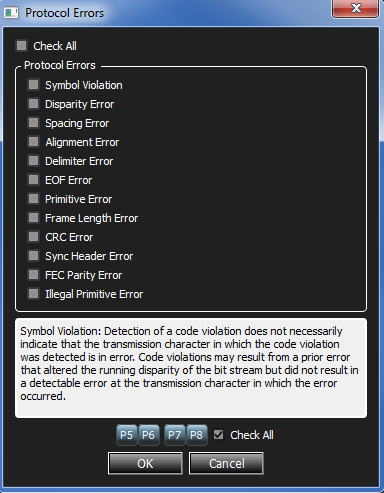
Select the desired protocol errors or click on the Check All box to select all the errors. Enter the count of the expected number of occurrences. Check the Check All box to select ports P1 through P8 or individually select ports.