
The X240/X500/X500e/X700 Logic Analyzer Pods are designed for use with TTL voltage levels, 0 to 3.3 volts maximum. Exceeding the 3.3 volts maximum may damage the pods.
X240 supports up to 2 HCI connections and 16 logic signals using two channel Pods. X500/X500e/X700 - Supports up to 2 HCI connections and 24 logic signals using three channel Pods.
To capture UART, SPI, I2S and logic data at the Bluetooth Host Controller processor interface using a wired connection:
-
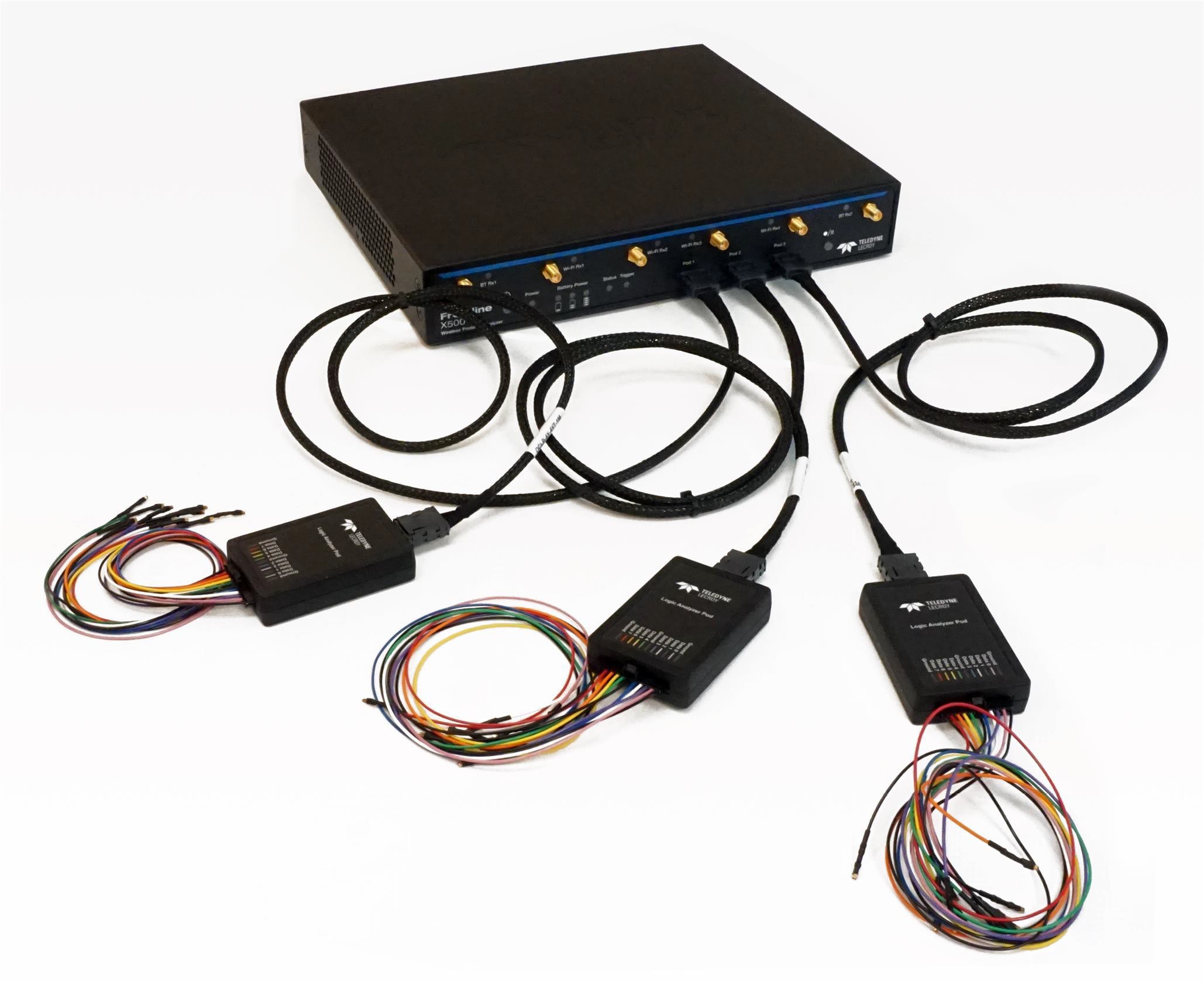
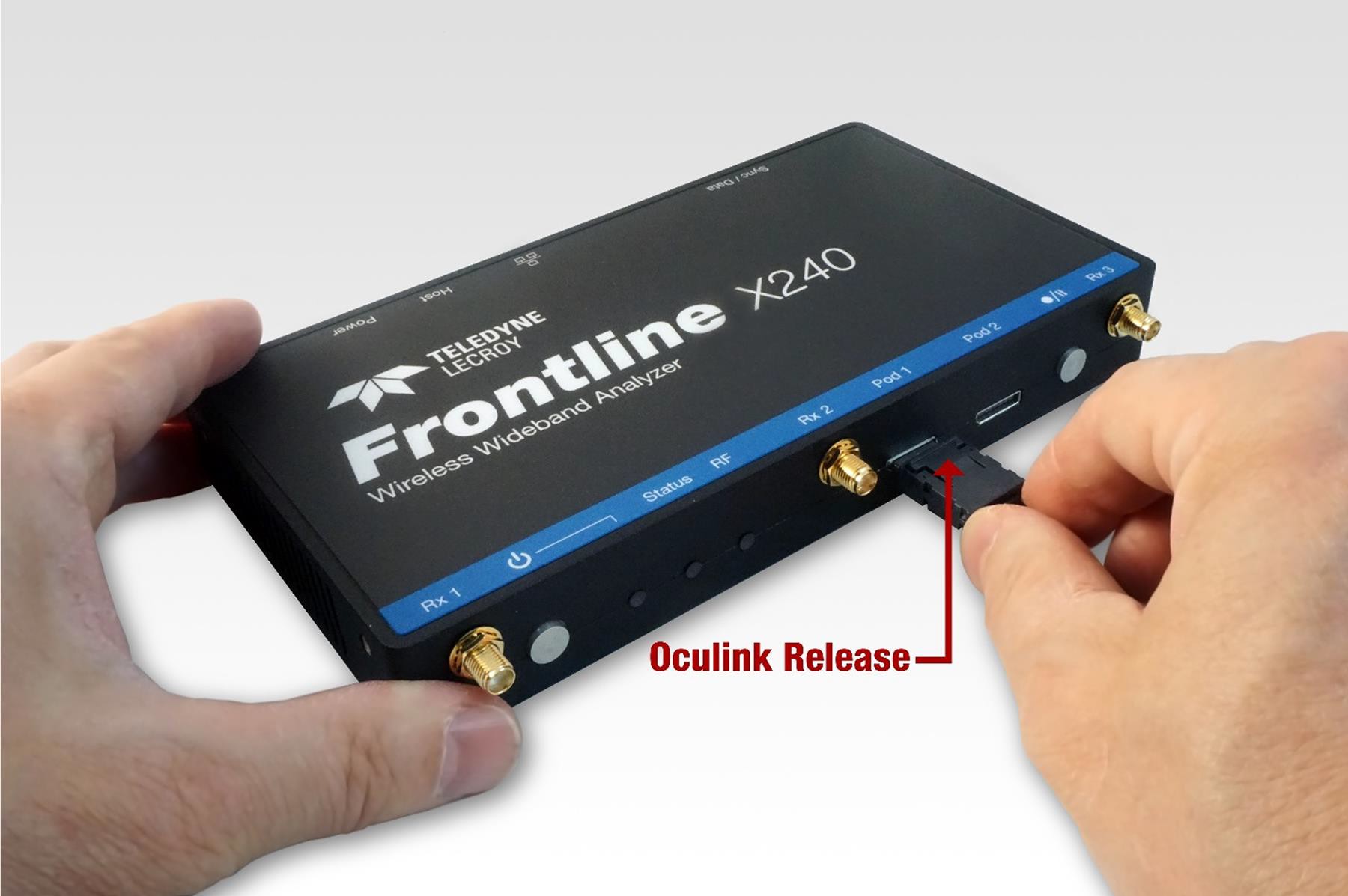
Connect a Logic Analyzer Pod to one of the Oculink connectors on the front panel of the X240/X500/X500e/X700. A Logic Analyzer Pod can be connected to either Oculink connector or two pods can be connected to both Oculink connectors at the same time.
-
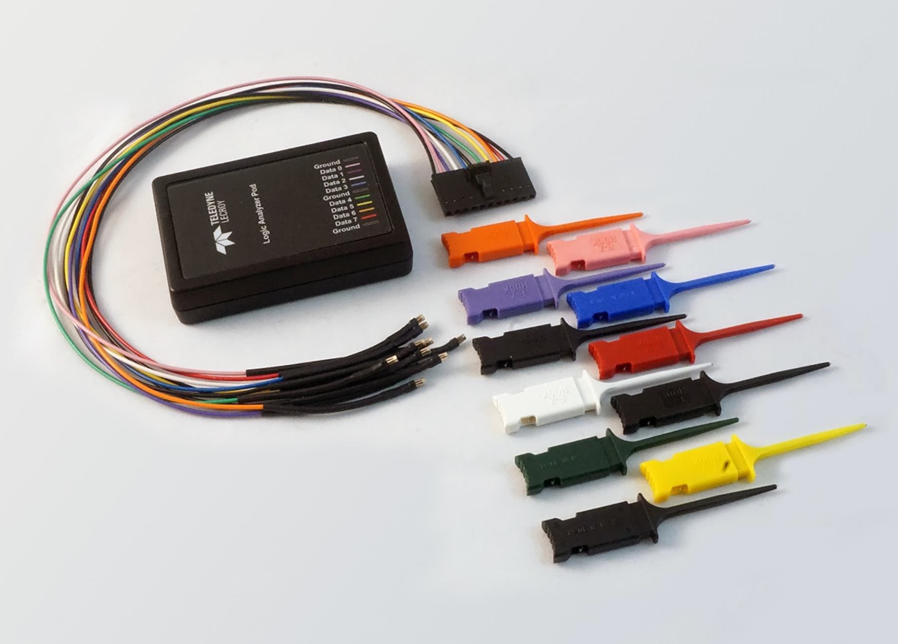
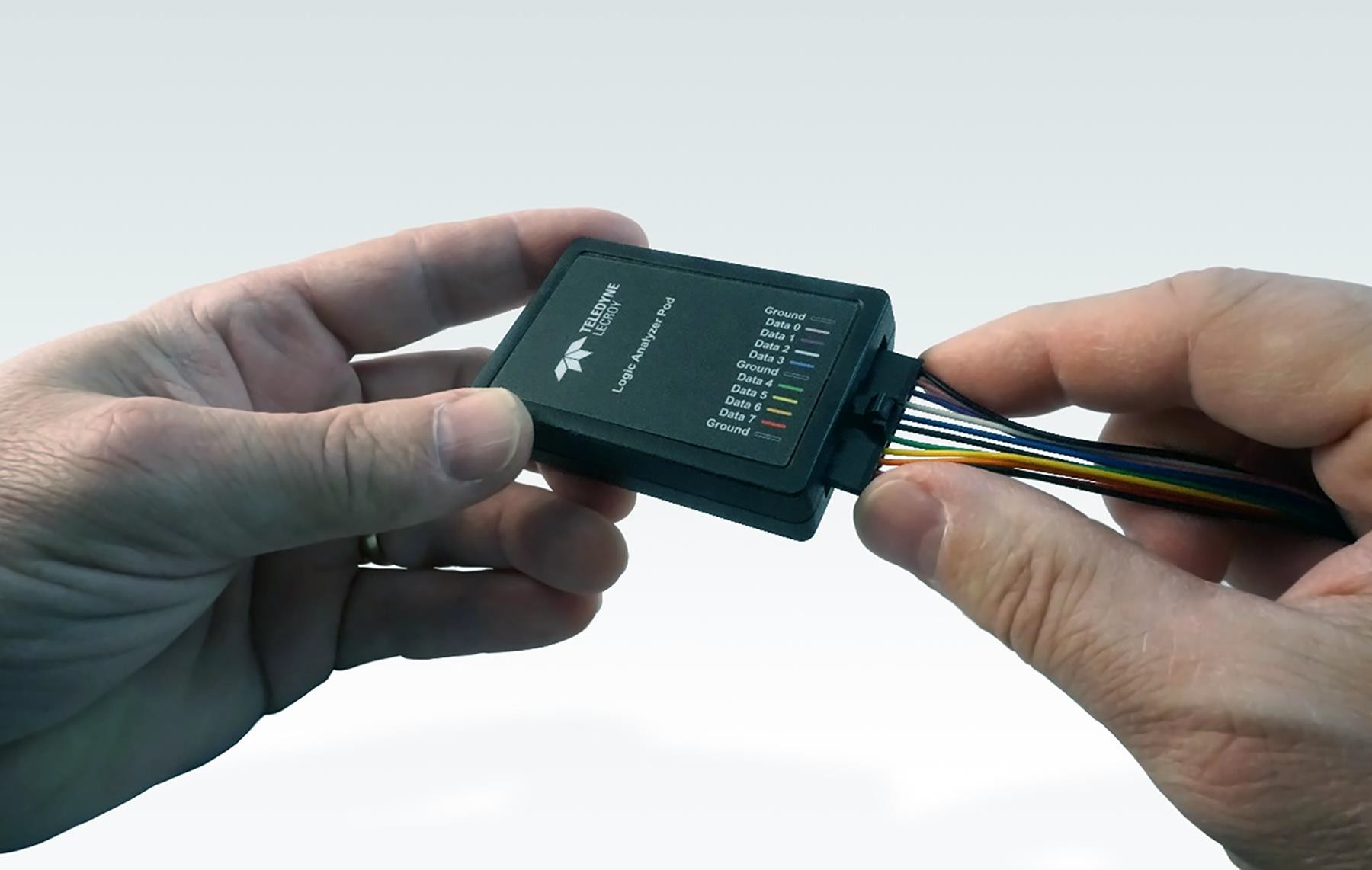
Attach the Flying Lead assembly to the end of the Logic Analyzer Pod. The connector is keyed to ensure proper installation.
-
Attach an appropriate Flying Lead Assembly micro-clip to the Bluetooth logic or HCI signal test point in accordance with the following table.
Logic Analyzer Pod Interface Pins
|
Pin |
Label |
|
1 |
Ground |
|
2 |
Data 0 |
|
3 |
Data 1 |
|
4 |
Data 2 |
|
5 |
Data 3 |
|
6 |
Ground |
|
7 |
Data 4 |
|
8 |
Data 5 |
|
9 |
Data 6 |
|
10 |
Data 7 |
|
11 |
Ground |
-
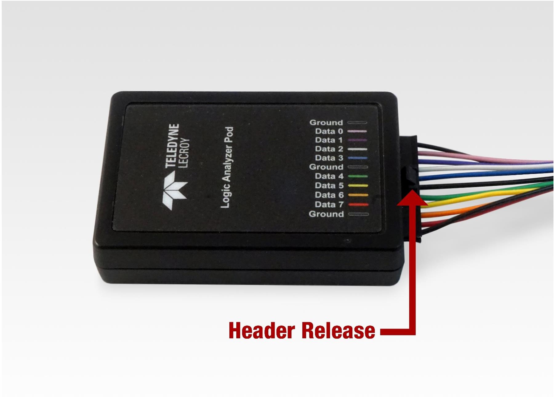
To remove the Flying Lead Assembly from the Logic Analyzer Pod, depress the release key on the Flying Lead Assembly.
-
To remove the Logic Analyzer Pod, depress the release key on the Oculink connector.
UART Capture Configuration
Successful HCI UART capture requires the following Logic Analyzer Pod connections.
Required UART Layer Connections
|
UART Signal |
Logic Analyzer Pod Pin |
Comment |
|
Tx |
Any single line labeled Data 0 through Data 7 |
Connect to the Device Under Test (DUT) TX pin. Only 1 data pin can be used. That pin cannot be used for Rx. Also, select this pin in the Wired tab of the Record Options. |
|
Rx |
Any single line labeled Data 0 through Data 7 |
Connect to the DUT Rx pin. Only 1 data pin can be used. That pin cannot be used for Tx. Also, select this pin in the Wired tab of the Record Options. |
|
GND |
Any line labeled Ground |
Any of the three Ground pins can be used to connect the DUT ground to the Logic Analyzer Pod. |
For more information, refer to the Wired Record Options.
Logic Event Capture Configuration
Successful logic event capture requires the following Logic Analyzer Pod connections. The Logic Analyzer Pod has up to eight pins that can be used for logic event capture.
Logic is internally limited to capturing less than 40,000 transitions per second to prevent sluggishness in WPS real-time captures. These transitions can occur at a rate up to 1 MHz reliably.
Required Logic Connections
|
Logic Signal |
Logic Analyzer Pod Pin |
|
0 |
Data 0 |
|
1 |
Data 1 |
|
2 |
Data 2 |
|
3 |
Data 3 |
|
4 |
Data 4 |
|
5 |
Data 5 |
|
6 |
Data 6 |
|
7 |
Data 7 |
|
GND |
Any line labeled Ground |
The above are TTL logic inputs for data. Select the corresponding pins in the Wired tab. For more information, refer to the Record Options in the Wired Tab.
For grounding, any of the three Ground pins can be used to connect the DUT ground to the Logic Analyzer Pod.
SPI Capture Configuration
Successful HCI SPI capture requires the following Logic Analyzer Pod connections.
Required SPI Connections
|
SPI Signal |
Logic Analyzer Pod Pin |
Comment |
|
SCLK |
Any single line labeled Data 0 through Data 7 |
Connect to the Device Under Test (DUT) SCLK pin. Only 1 data pin can be used. |
|
MOSI |
Any single line labeled Data 0 through Data 7 |
Connect to the Device Under Test (DUT) MOSI pin. Only 1 data pin can be used. |
|
MISO |
Any single line labeled Data 0 through Data 7 |
Connect to the Device Under Test (DUT) MISO pin. Only 1 data pin can be used. |
|
SS/CS |
Any single line labeled Data 0 through Data 7 |
Connect to the Device Under Test (DUT) SS/CC pin. Only 1 data pin can be used. |
|
GND |
Any line labeled Ground |
Any of the three Ground pins can be used to connect the DUT ground to the Logic Analyzer Pod. |
I2S Capture Configuration
The Inter-IC Sound Bus (I2S) was designed to transport a multi-channel digital audio signal between circuit components on a single printed circuit board.
Successful HCI I2S capture requires the following Logic Analyzer Pod connections.
Required I2S Connections
|
I2S Signal |
Logic Analyzer Pod Pin |
Comment |
|
SCLK |
Any single line labeled Data 0 through Data 7 |
Connect to the Device Under Test (DUT) SCLK pin. Only 1 data pin can be used. |
|
FS |
Any single line labeled Data 0 through Data 7 |
Connect to the Device Under Test (DUT) FS pin. Only 1 data pin can be used. |
|
DS |
Any single line labeled Data 0 through Data 7 |
Connect to the Device Under Test (DUT) DS pin. Only 1 data pin can be used. |