
Front Panel Controls and Connections
The Frontline X700 front panel is shown below. The panel provides controls to power up and shut down the Frontline X700 hardware, and it provides indicators to show the power and capture status.
Front Panel Connections and Status Indicators
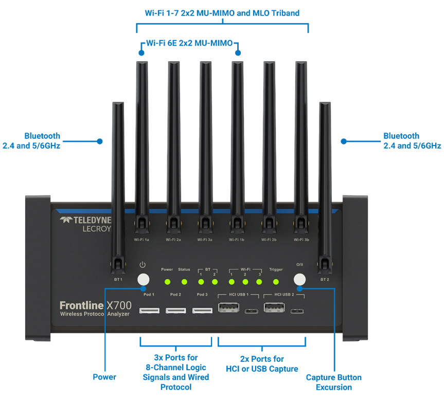
Power Button: Press and release the button to power on/off the system.
Capture Button for eExcursion Mode: The capture button for excursion captures illuminates when the unit is connected to a power source. Pressing this button will begin data capture - the same as the Record button in the Wireless Protocol Suite. The eExcursion Mode button is inactive when X700 is connected to a computer.
To operate in eExcursion mode, the X700 hardware must have been previously configured from the Wireless Protocol Suite prior to disconnecting from the computer. The X700 hardware will retain the configuration settings when disconnected from the computer. Refer to the Wireless Protocol Suite Hardware and Software User Manual for eExcursion Mode operating details.
PODs with Oculink Connectors: There are 3 PODs to connect 8 channel logic cable to capture HCI UART/SPI/I2S and logic signals.
HCI USB 1/HCI USB 2: USB Type A and USB Type C connectors allow capture of HCI USB data.
Antenna SMA Connectors: Antenna attaching point for Bluetooth and Wi-Fi capture.
Status Indicators: Colored LEDs show the status of power, capture and RF status.
Frontline X700 Front Panel Status Indicators
|
Indicator |
Color |
State |
Status Indicated |
|
Power |
None |
Off |
Unit is powered off. |
|
Green |
Constant |
Unit is ON and ready. |
|
|
Red |
Fast Flash |
Thermal warning threshold reached. |
|
|
Constant |
System reaches thermal overload. Unit has started a controlled/sequenced power down. |
||
|
Status |
None |
Off |
No status. |
|
Green |
Constant |
Initialized and Ready (Not capturing). |
|
|
Blue |
Constant |
Actively capturing. |
|
|
Yellow |
Slow Flash |
Initializing. |
|
|
Fast Flash |
Shutting down. |
||
|
Red |
Constant |
Unit failed to initialize or has a System Error. |
|
|
Purple |
Constant |
Recovery Mode. |
|
|
BT Link 1 |
None |
Off |
Antenna not in use. |
|
Green |
Constant |
Antenna in use and capturing. |
|
|
Red |
Constant |
Signal strength is too strong. |
|
|
BT Link 2 |
None |
Off |
Antenna not in use. |
|
Green |
Constant |
Antenna in use and capturing. |
|
|
Red |
Constant |
Signal strength is too strong. |
|
|
Wi-Fi Link 1 |
None |
Off |
Antenna not in use. |
|
Green |
Constant |
Antenna in use and capturing. |
|
|
Wi-Fi Link 2 |
None |
Off |
Antenna not in use. |
|
Green |
Constant |
Antenna in use and capturing. |
|
|
Wi-Fi Link 3 |
None |
Off |
Antenna not in use. |
|
Green |
Constant |
Antenna in use and capturing. |
|
|
Trigger |
Blue |
Slow flash |
Waiting for Trigger. |
|
Constant |
Triggered. |
||
|
Red |
Constant |
Error detected. |
|
|
None |
Off |
No activity. |
Rear Panel Connections
The rear panel is shown below. The panel provides connectors for external power and for a connection to the computer hosting the Wireless Protocol Suite software.
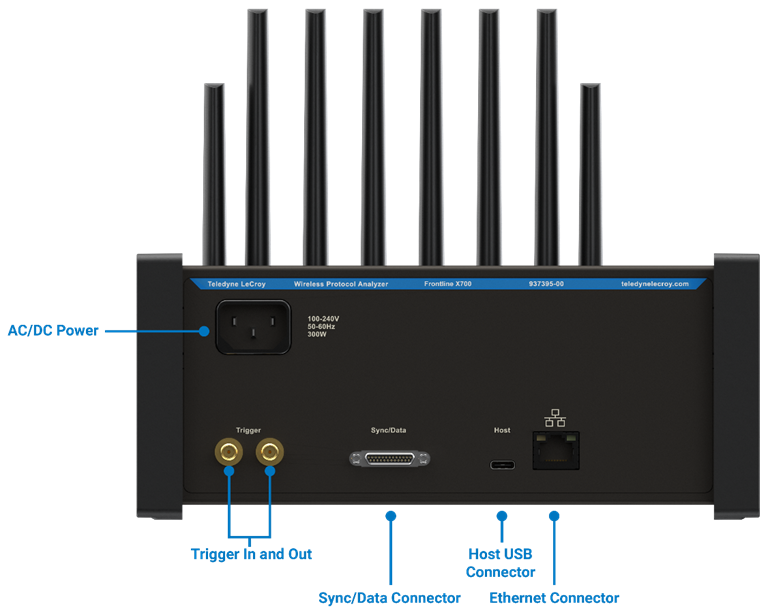
Power: The Frontline X700 uses a AC/DC supply of 125V-10A.
Trigger In and Out: Reserved for future use.
Sync/Data Connector: The MicroD25 connector will be used in a future release to connect multiple X700s or other PSG analyzers to capture time synced data using CrossSync technology.
Host: USB C 3.0 port for connecting X700 to the host computer where the Wireless Protocol Suite resides. This connector provides host computer command, control, and data transfer.
Please use the Teledyne-provided USB 3.1 cable to connect to the computer. Using a cable with lower specifications may lead to issues launching and running the Wireless Protocol Suite software.
Ethernet: Ethernet connector for communication with the host computer where the Wireless Protocol Suite resides. This connector provides host computer command, control and data transfer.
Attaching Antennas
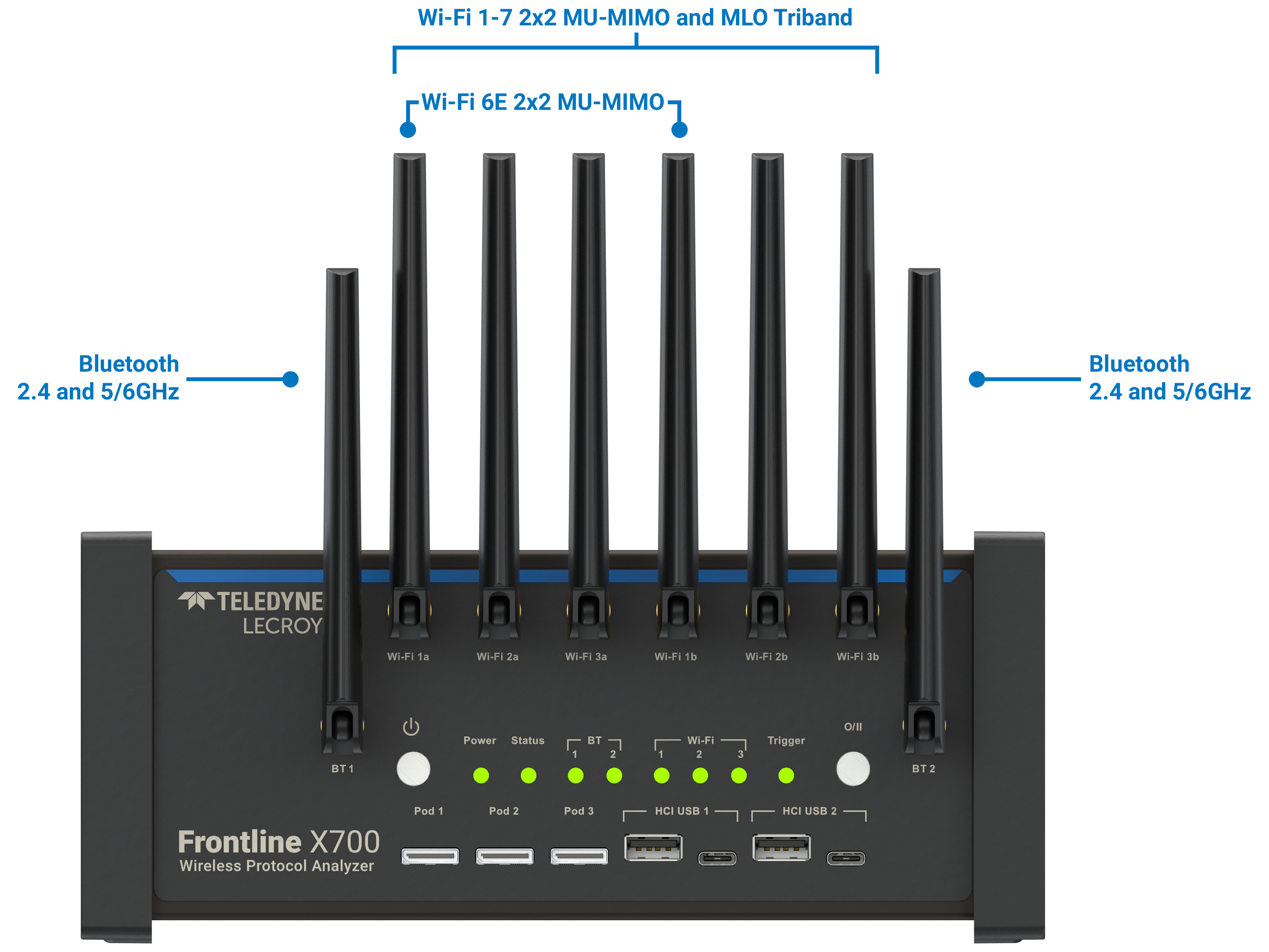
Remove the Frontline X700 hardware from the box and attach the eight antennas to the SMA connectors on the front panel. As the names indicate, BT 1 and BT 2 are Bluetooth antenna connectors. For capturing Wi-Fi, there are three Wi-Fi radios (1, 2, and 3) where each have two antennas (a and b). All three radios support Wi-Fi 7 2x2. If the X700 is licensed for Wi-Fi 6E, Radio 1 will be used with the corresponding antennas, 1a and 1b.
The base of the antennas can be carefully rotated by 90 degrees so that the antenna points upward.
The nuts for RF Antenna SMA connections should not be tightened beyond 1 in-lb of torque.
The X700 is configured to use Antenna Diversity for capture to intelligently improve performance and eliminate the need to place the unit in a specific position when wireless channels are affected by multipath, fading, and interference. See Capturing Data for more information about Antenna Diversity.
Applying Power
Connect the 125V supplied power cable supplied to the X700 hardware. To turn on the X700 hardware, press and release the Power button on the front panel. This will start the X700 hardware. The front panel antenna LEDs will blink green and the Status indicator LED will be solid green once the unit has completely booted up. If the front panel Power indicator blinks red, the X700 hardware is approaching thermal overload temperature, between 70° C and 80° C (158° F and 185° F), and should be shutdown. If the hardware reaches thermal overload, it will automatically shut down and the Power indicator will turn off.