
Go to Start > All Programs > LeCroy > USB Protocol Suite > USB Protocol Suite.
Note: The installer adds a service that helps keep your software up-to-date. If you see a message from your antivirus software, you can:
-
Disable your antivirus software until installation is complete
-
Opt out of automatic updates during installation
You can use the software with or without the system connected to the host machine. Without the analyzer, the program functions as a trace viewer to view, analyze, and print trace files.
Confirm Proper Hardware Installation & USB or Ethernet Connection
USB Connection
To confirm proper installation and USB connection:
-
Open the USB Protocol Suite application.
-
From the main menu, select Help > About. The Software Version, Firmware Version, BusEngine™ Version, and Unit Serial Number display in the About window.
Ethernet Connection (Voyager only)
For Ethernet connection, after you open the USB Protocol Suite application, confirm proper installation and Ethernet connection using the Analyzer Devices and the About windows.
Analyzer Devices Window
To show the available analyzer devices, select Setup > All Connected Devices. The Analyzer Devices window appears.
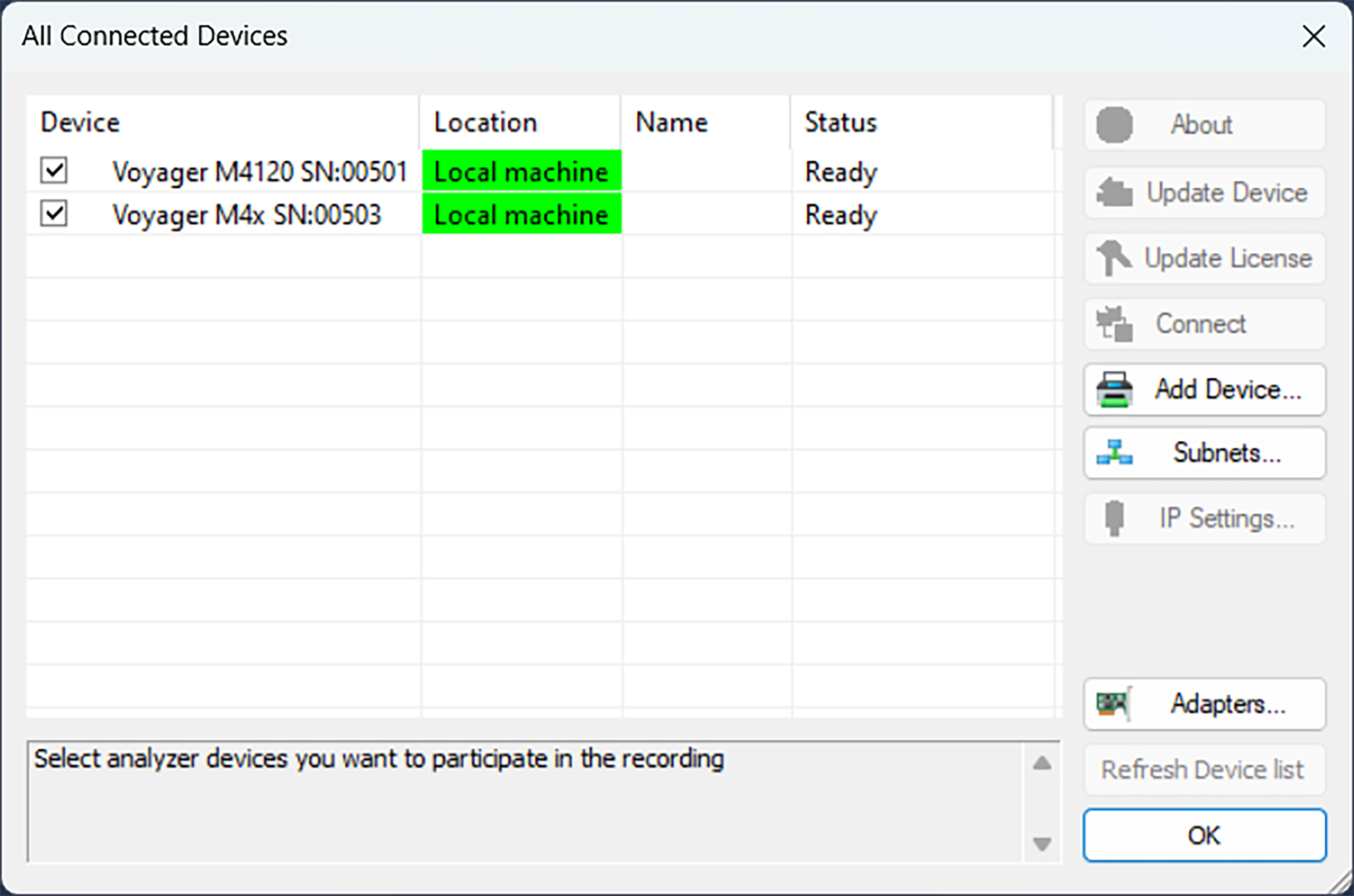
You can select:
-
About to display device information (see Software, Firmware, and BusEngine Revisions).
-
Update Device (see Manual Updates to Firmware, BusEngine, and Serdes BusEngine)
-
Update License (see Updating the Software License)
-
Connect to open the Connection Properties window, where you can set the system to:
-
Automatically connect to the device
-
Ask to connect to the device
-
Take no action
-
-
Add Device to open the Add Ethernet Attached Device window, where you can enter an IP Address
-
IP Settings to use a DHCP or Static IP address
-
To refresh the list of devices, click Refresh Device List
-
Before starting a recording, select the analyzer you want to use.
IP Settings (Voyager only)
If connected to a device, you can change the IP settings:
-
DHCP automatically assigns an IP address. DHCP is the default.
-
Static IP prompts you to enter a specific IP address. To change from DHCP to Static IP while connected to a device:
-
Select Setup > All Connected Devices from the menu bar. The Analyzer Devices window opens.
Note: If you are not connected to a device, the IP Settings command is inactive.
-
Select the device to use in the recording, then click the IP Settings button to display the Device IP Settings dialog box.
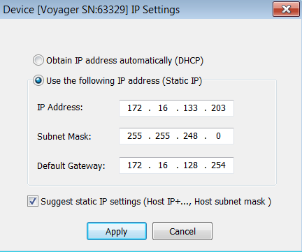
Two radio buttons are available:
-
Obtain IP address automatically (DHCP) [default]
-
Use the following IP Address (Static IP)
-
To change to Static IP, click the Static IP radio button, then:
-
Enter the IP Address.
-
Enter the Subnet Mask.
-
Enter the Default Gateway.
-
-
Click Apply. A success message appears and you are returned to the analyzer Devices window.
-
Click Close to close the window and use the device with a Static IP address.
The system can also Suggest static IP settings (IP address and subnet mask).
Signal Parameters
The methods and interfaces for setting signal parameters vary based on the particular analyzer you’re using.
Voyager M4120, Voyager M480x
USB4 Gen 4 Receiver Tuning
Voyager M4120 and Voyager M480x use receiver tuning to automatically optimize the unit’s PAM3 receiver settings for the connected USB4 Gen 4 test setup. Run receiver tuning before capturing USB4 Gen 4 traffic. Receiver tuning is setup optimization; it is not a periodic hardware calibration or a USB compliance test.
Important: A tuning profile is specific to the analyzer or Exerciser unit, host or device, cables, analyzer ports, link configuration, and transmitter settings used during tuning. Run receiver tuning again if any of these change, including when the same test setup is moved to a different analyzer unit. Earlier software releases called this feature Auto Calibration.
In Analyzer mode, receiver tuning changes only the analyzer’s receive settings. It does not tune the host or device, change the pass-through signal path between them, or certify the electrical quality of the link. In Exerciser mode, it tunes the Exerciser receiver.
Before You Start
-
Connect the host and device through the analyzer and establish the link in USB4 Gen 4 CL0. For Exerciser tuning, connect the port under test (PUT) to the Exerciser port.
-
Use short, low-loss, high-quality cables. Receiver tuning can optimize the receiver for a viable signal, but it cannot compensate for a fundamentally poor or unstable signal path.
-
Leave the host, device, cables, and analyzer ports unchanged while tuning runs. Tuning may reset or retrain the link; allow the devices to return to CL0 without manually disconnecting the setup.
-
Allow sufficient time. Depending on signal quality, receiver tuning can take from several minutes to more than an hour.
-
Confirm that the unit has the appropriate USB4 Gen 4 Analyzer or Exerciser license.
Configuration Choices
|
Product and mode |
Configuration |
|---|---|
|
Voyager M4120 Analyzer |
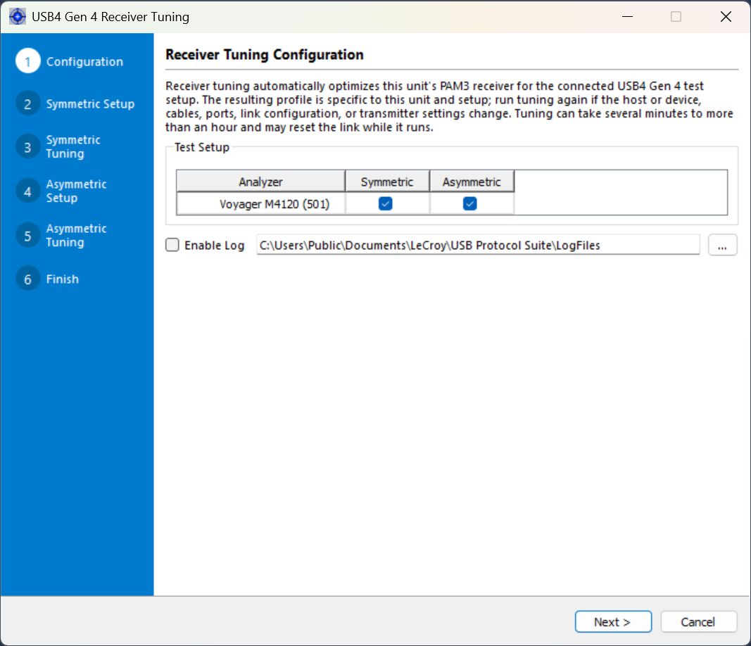
Select Symmetric, Asymmetric, or both. If both are selected, the wizard tunes the symmetric link first and then prompts you to reconfigure the link for asymmetric tuning. |
|
Voyager M480x Analyzer |
Select Analyzer. The wizard handles the analyzer receiver paths automatically. |
|
Voyager M480x Exerciser |
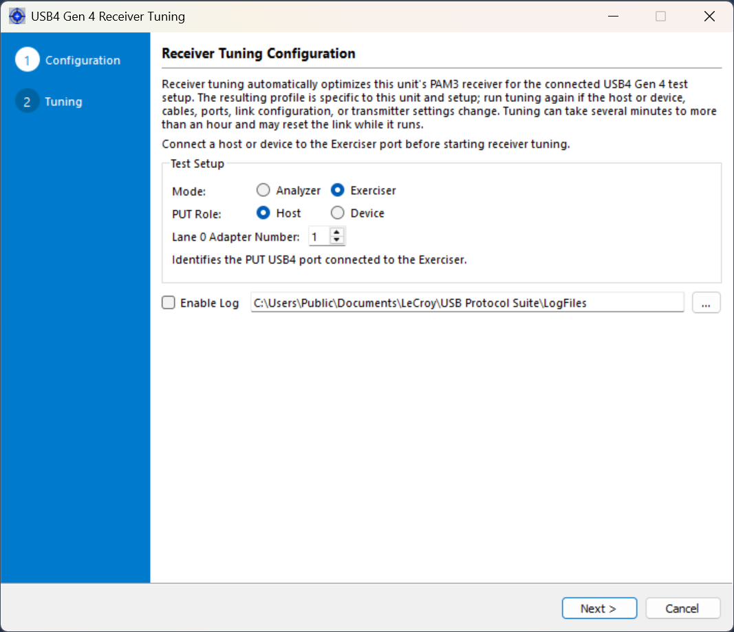
Select Exerciser, select whether the PUT is a host or device, and enter the Lane 0 Adapter Number for the connected USB4 port. The adapter number is typically 1 for a device and 1, 3, 5, or 7 for successive host or hub ports. |
Run Receiver Tuning
-
In the status bar, select the target icon next to the unit to tune.

-
The USB4 Gen 4 Receiver Tuning wizard opens. Review the setup-specific guidance, choose the applicable configuration, and select Next.
-
The tuning stage starts automatically. Keep the setup connected and follow any prompts to establish the requested link configuration. Do not close the wizard, change the setup, or start a recording while tuning is in progress.
-
When tuning completes, review the result for each receiver path. A completed process is not necessarily a passing result; use the result definitions below.
-
Save the receiver settings as a new profile, or, when available, add them to an existing profile. Record the connected DUTs, cables, and any identifying setup details in the profile fields.
Interpret the Results
|
Result or status |
Meaning and action |
|---|---|
|
Pass |
The receiver settings met the tuning criteria for the indicated path. Save the profile and use it only with the setup for which it was created. |
|
Marginal |
The best settings found did not meet the pass criteria. Capture may still be possible, but reliability is not guaranteed. Check the connections, use shorter or higher-quality cables, confirm the intended link configuration, and run receiver tuning again. If you save a marginal profile for investigation, identify it clearly in the profile name or notes. |
|
---- |
The path was not selected for tuning or no result applies to that path. |
|
Stopped, aborted, timeout, or unresponsive process |
Tuning did not produce a complete, validated result. Restore a stable Gen 4 CL0 link and rerun receiver tuning. Do not rely on partially determined settings. |
Note: A Pass result indicates that the receiver-tuning criteria were met. It is not a USB compliance result and does not guarantee an error-free capture under every condition.
Troubleshooting Receiver Tuning
|
Symptom |
Recommended action |
|---|---|
|
The wizard does not continue from Configuration. |
For M4120, select at least one link configuration. Confirm that the unit has the required USB4 Gen 4 license. |
|
The link does not establish or return to Gen 4 CL0. |
Confirm that the host, device, and cables support USB4 Gen 4; verify that the actual link matches the selected symmetric or asymmetric configuration; reconnect the setup; and retry with short, known-good cables. |
|
The result is Marginal. |
Check connector seating and cable quality, avoid unnecessary adapters, and rerun tuning without changing the setup. A consistently marginal result may indicate that the connected signal path does not provide sufficient receiver margin. |
|
Tuning stops with a timeout or an unresponsive-process message. |
Restore the Gen 4 CL0 link, close and reopen the wizard, and retry. If the problem repeats, leave Enable Log selected and provide the generated log folder to Teledyne LeCroy support. |
|
Capture quality is poor after a Pass result. |
Confirm that the matching profile is applied to the same unit and unchanged setup. If anything changed or the problem remains, run receiver tuning again and inspect the test setup for signal-integrity problems. |
Profiles
Receiver tuning programs the connected unit with the settings it finds. Saving those settings creates a reusable profile for later sessions.
-
Treat every tuning profile as unit- and setup-specific. Run receiver tuning separately for each analyzer or Exerciser unit.
-
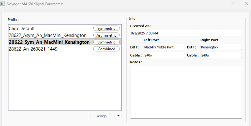
Use the DUT, Cable, and Notes fields to identify the host, device, cables, analyzer ports, link configuration, transmitter settings, and any relevant test conditions.
-
For M4120, selecting both link configurations creates a profile containing symmetric and asymmetric receiver settings. If you tune only one configuration, you can save it separately or add it to a profile that contains the other configuration. The wizard warns before replacing settings in an existing combined profile.
-
Each profile is labeled Symmetric, Asymmetric, or Combined to show which link configurations it contains. The same labels appear in the profile list on the last page of the receiver tuning wizard.
-
Saving a Marginal result does not convert it to a Pass. Record that status in the profile name or notes.
-
Select Setup > Signal Parameters to open the Signal Parameters window for the connected M4120 or M480x.
-
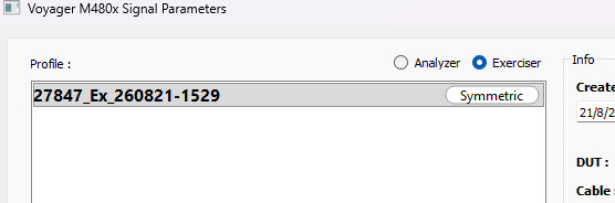
Select Analyzer or Exerciser to list the profiles tuned in that mode. The selection follows the mode currently set in Setup > Recording Options.
Voyager M480x Profile Mode Selection -
Select the profile that matches the connected unit and test setup, then select Save and Apply.
Note: Use the profile’s Notes, DUT, and Cable fields to verify that it matches the current setup before applying it.
Right-click in the Profiles list for additional actions, including Delete, Rename, and Assign.
Voyager M4x (USB4 and USB 3.2)
To select values for the Rx Equalizer Settings for the M4x, go to Setup > Signal Parameters > M4x. The M4x Signal Settings window opens.
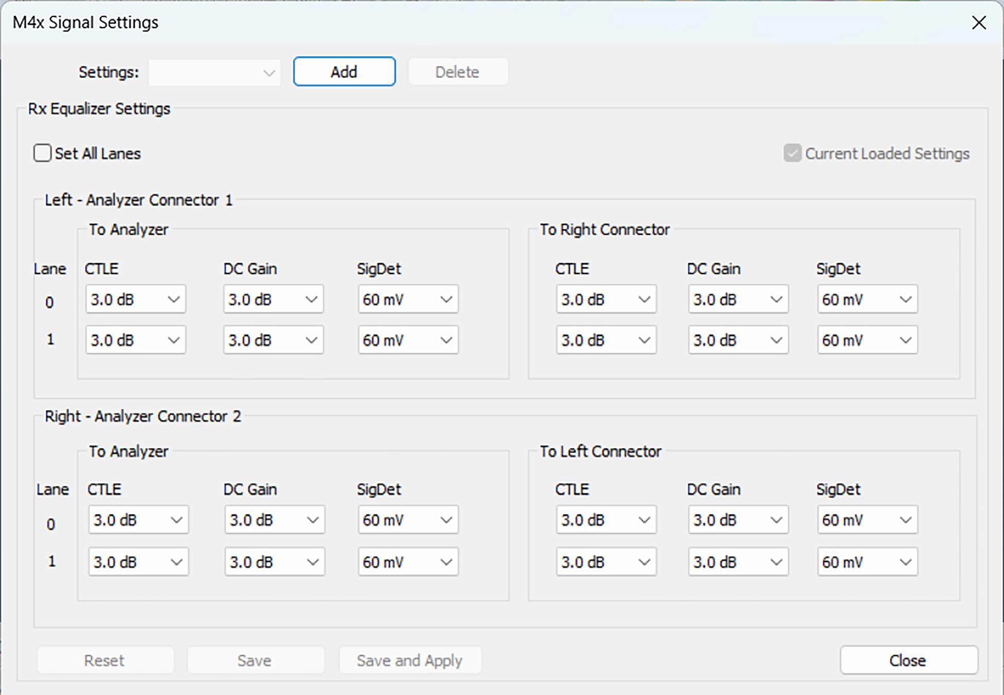
Use this window to:
-
Rx Equalizer Settings: Set All Lanes or Set Lane 0 and Lane 1 to different values.
-
Set the values for Left – analyzer Connector 1:
-
To analyzer
-
CTLE Values: From 0.0 dB to 6.0 dB in 0.2 dB increments
-
DC Gain Values: From 0.0 dB to 6.0 dB in 0.2 dB increments
-
SigDet Values: From 30 mV to 410 mV in varying increments
-
-
To Right Connector
-
CTLE Values: From 0.0 dB to 6.0 dB in 0.2 dB increments
-
DC Gain Values: From 0.0 dB to 6.0 dB in 0.2 dB increments
-
SigDet Values: From 30 mV to 410 mV in varying increments
-
-
-
Set the values for Right – analyzer Connector 2:
-
To analyzer
-
CTLE Values: From 0.0 dB to 6.0 dB in 0.2 dB increments
-
DC Gain Values: From 0.0 dB to 6.0 dB in 0.2 dB increments
-
SigDet Values: From 30 mV to 410 mV in varying increments
-
-
To Left Connector
-
CTLE Values: From 0.0 dB to 6.0 dB in 0.2 dB increments
-
DC Gain Values: From 0.0 dB to 6.0 dB in 0.2 dB increments
-
SigDet Values: From 30 mV to 410 mV in varying increments
-
-
If you enter values for the Rx Equalizer Settings and select Add, the New Signal Settings box opens.
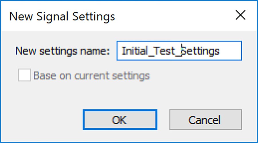
Click OK. The Initial Test Settings appear in the M4x Signal Settings window.
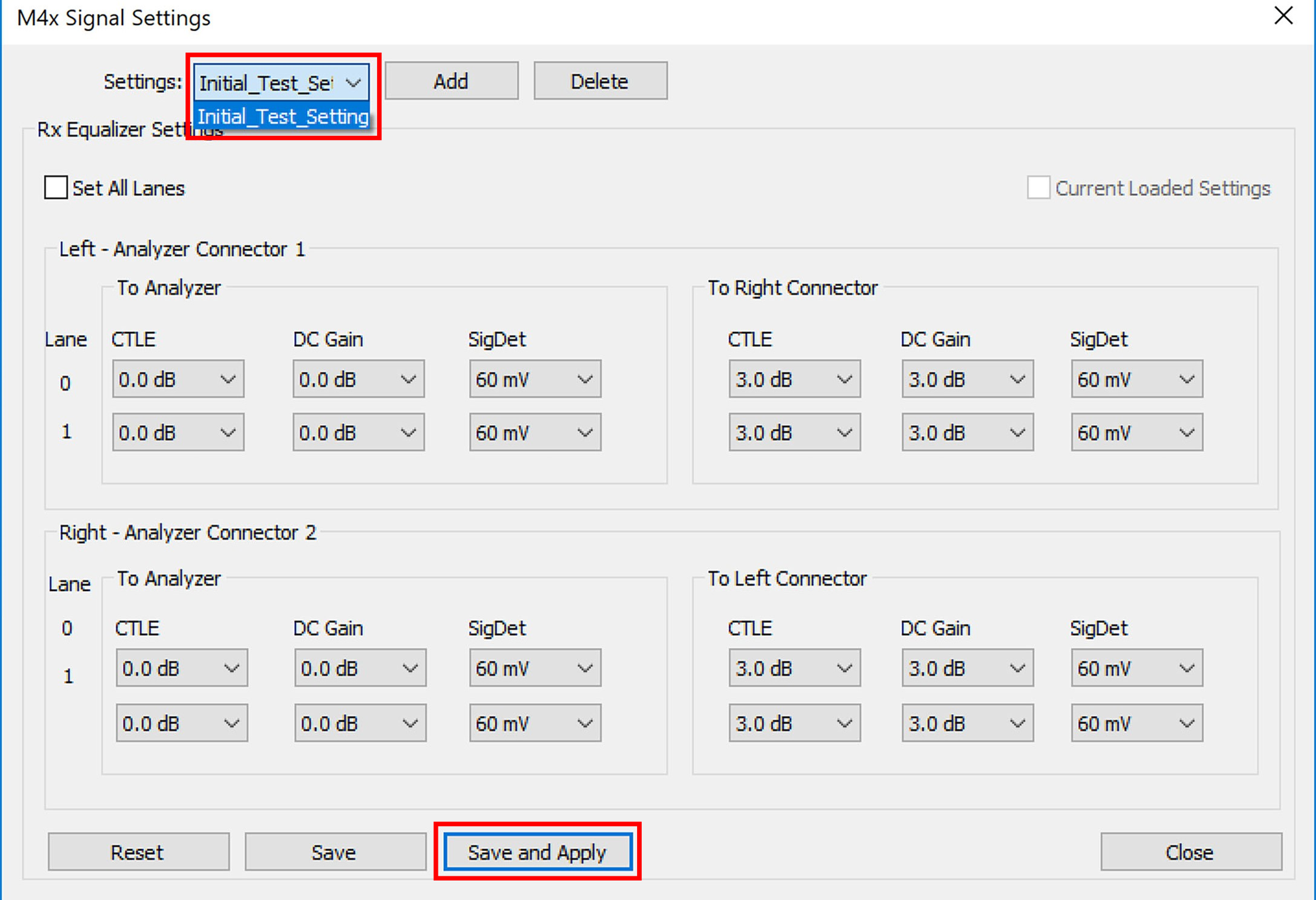
You can also Save and Apply, Reset, or Save the set of Rx Equalizer Settings values you have chosen. If you have more than one set of values you can Add that set or Delete it as well.
Rx Equalization Settings Detail & Troubleshooting Capture/Link Problems
The figure below shows how Rx Equalization setting are mapped to different paths in M4x analyzer front end.
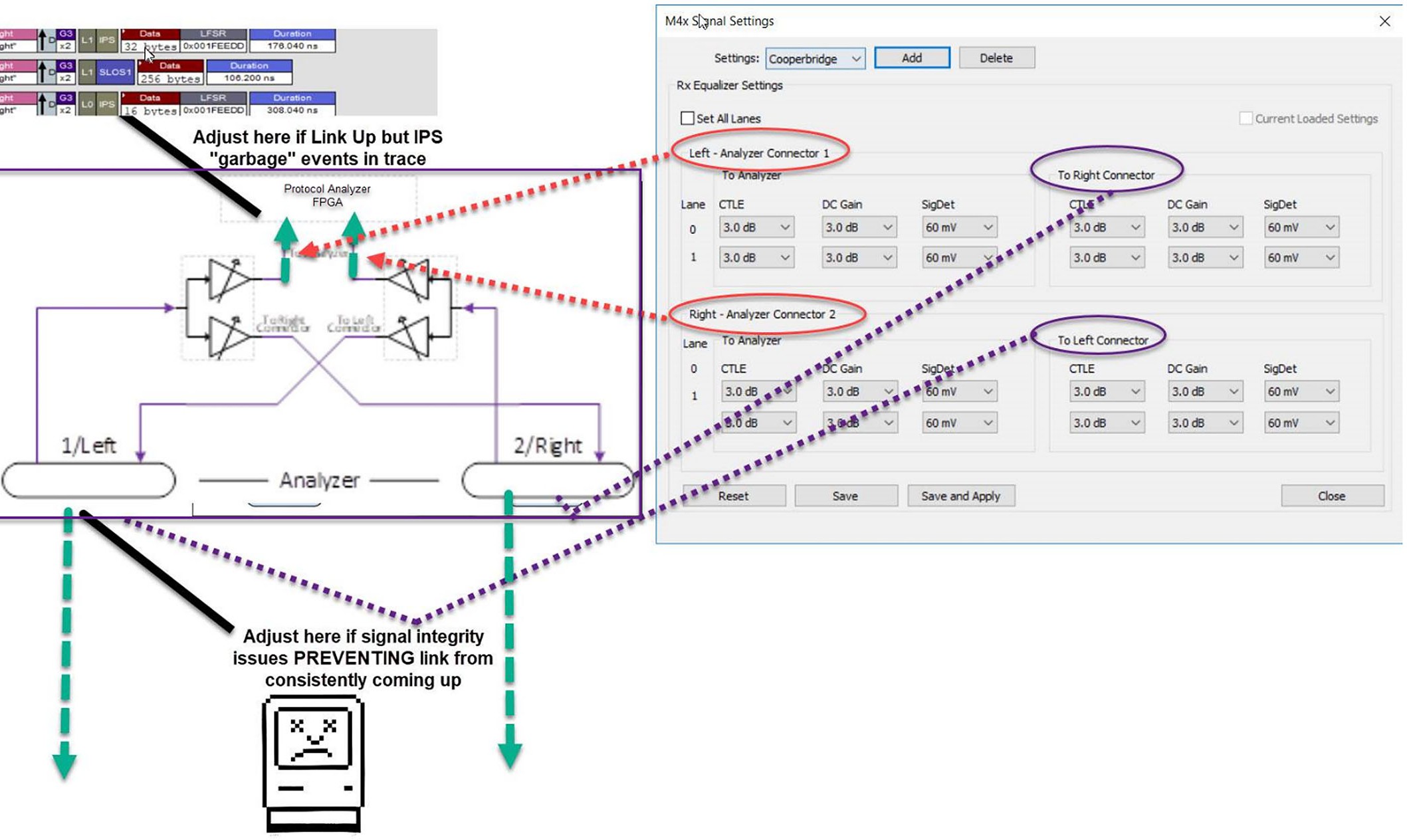
“To analyzer” settings are designated to tune settings for the path between attached DUTs and “protocol analyzer FPGA” (green arrows). Therefore, if the link between two DUTs are good but analyzer is capturing IPSs, you need to adjust these parameters:
-
If errors (IPS packets) are seen from “Left” in the captured trace, you need to change the settings for the left connector.
-
If errors are seen from “Right” in the captured trace, you need to change parameters for the right connector.
To Right Connector and To Left Connector settings are designated to tune settings for pass-through the path (between two DUTs), highlighted purple. If the link between DUTs is getting broken by putting the M4x analyzer in the middle of traffic, you need to adjust these parameters to create a successful link between the DUTs attached to both sides of analyzer.
Adding and Saving New Rx Equalization Settings
After you have updated the equalization settings you can Add or Save and Apply them with the buttons in the signal settings window, below.
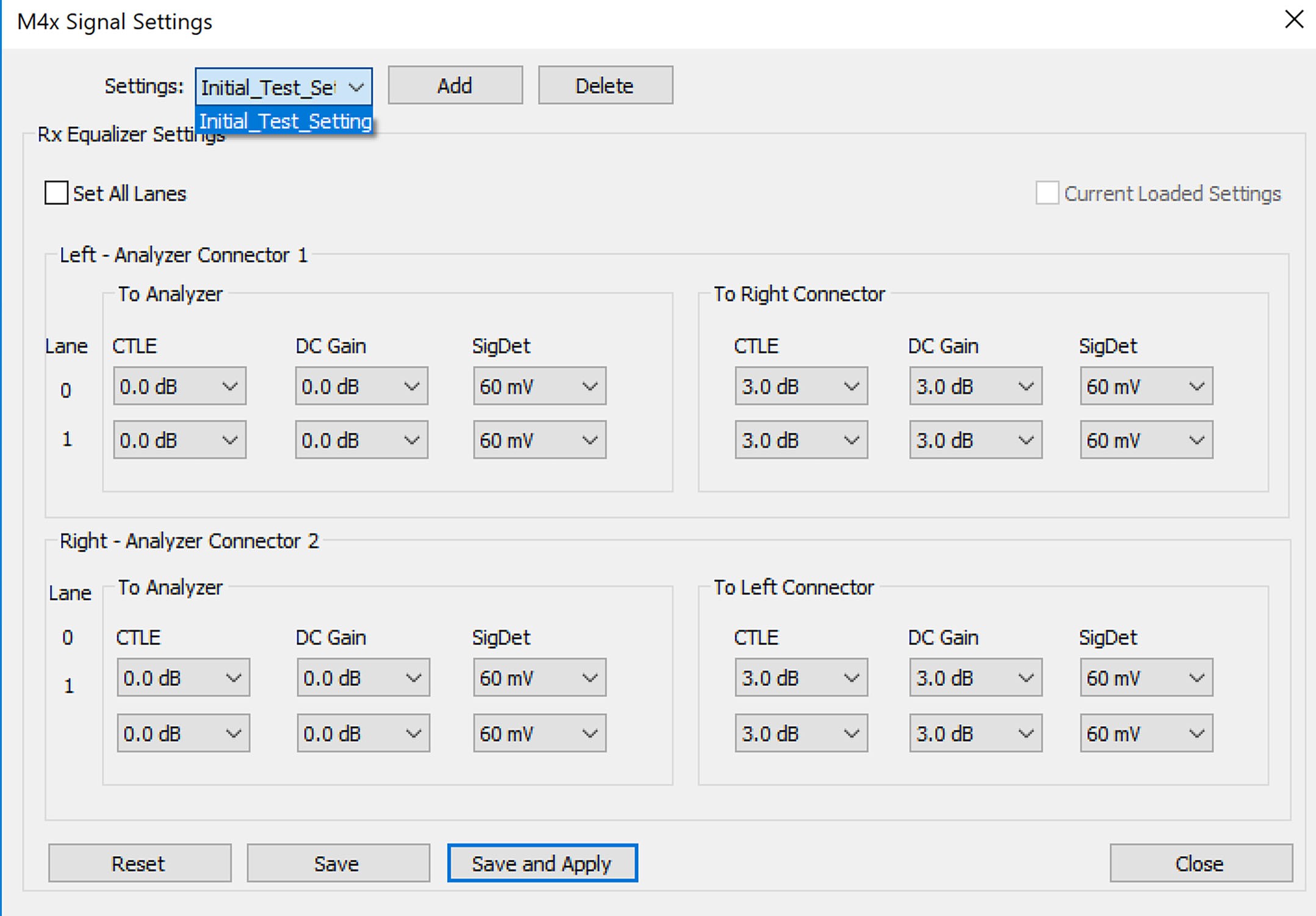
Using .csv Files (USB 3.2)
You can add, remove, edit, load (from a comma-delimited .csv file), or save (as a comma-delimited .csv file) USB 3.2 devices and to calibrate USB 3.2 connections:
Select Setup > Signal Parameters.
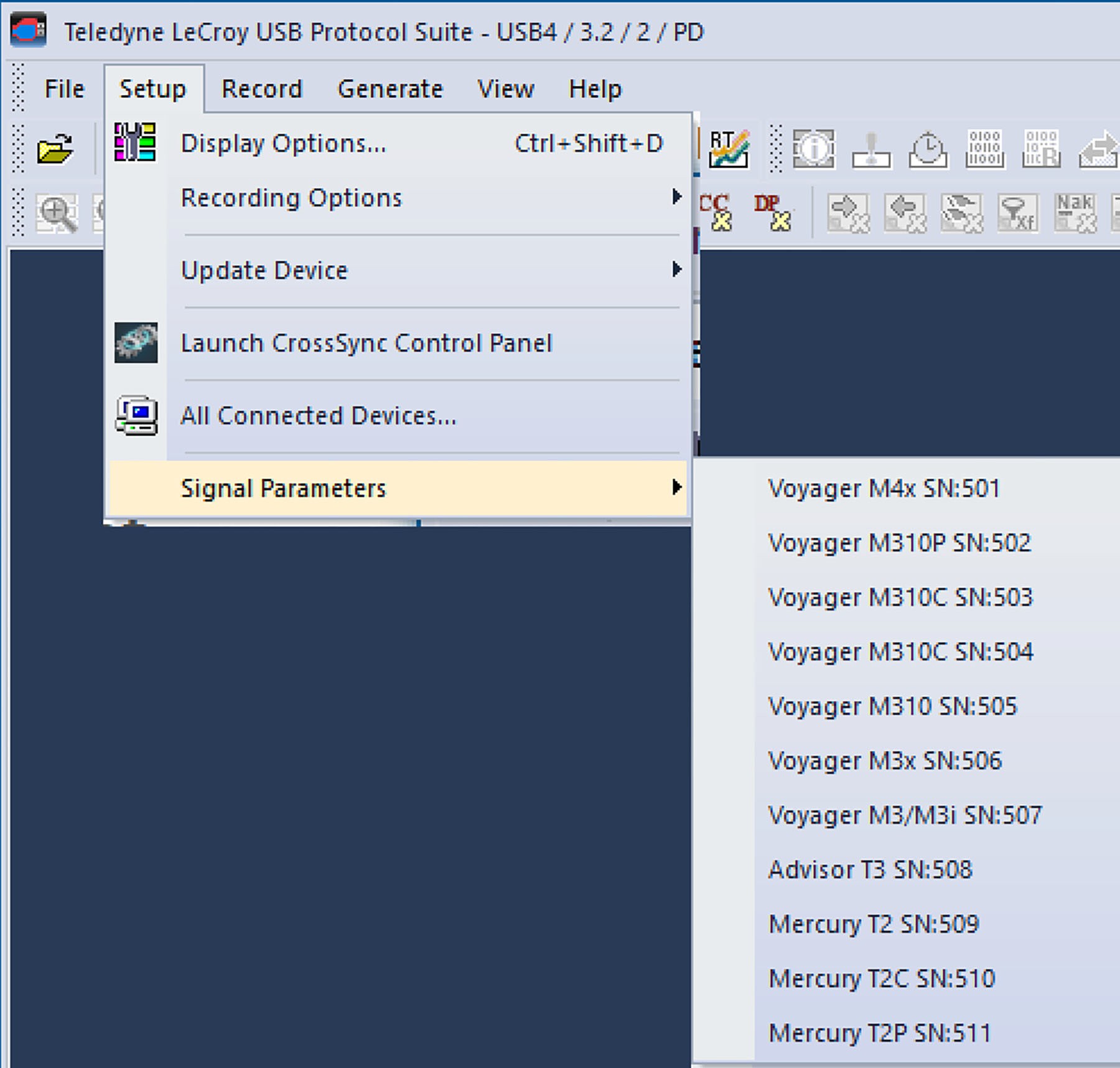
Select the USB 3.2 device you want to modify and/or for which to calibrate USB 3.2 connections.
The Host Signal Profiles window appears for the selected device.
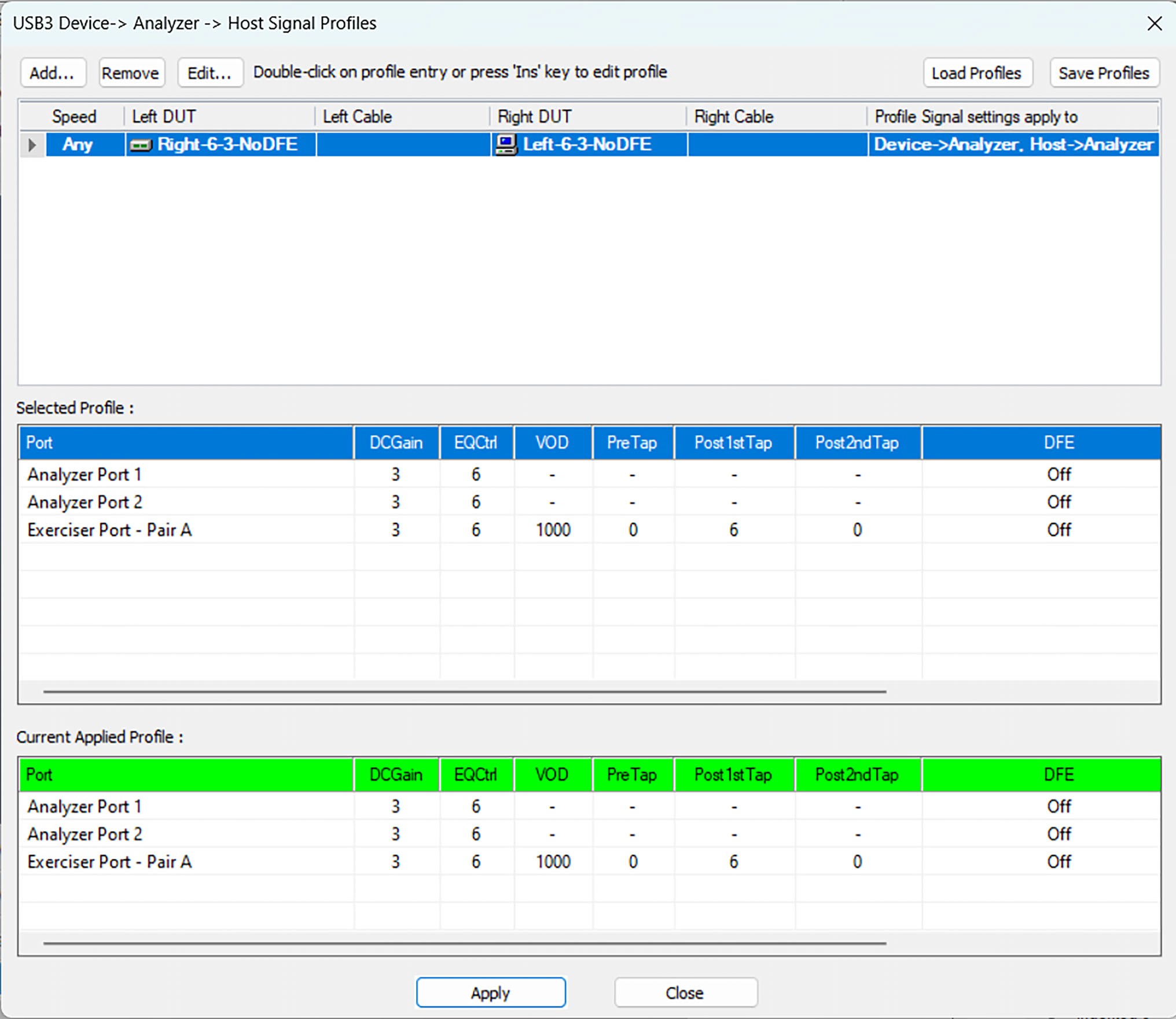
Choose Load Profiles, then select the .csv file for the profile you want to use.
Voyager M310 and M310C
To edit the Host Signal Parameters Profile of a specific profile entry, double click on the entry. The Host Signal Parameters Profile window appears.
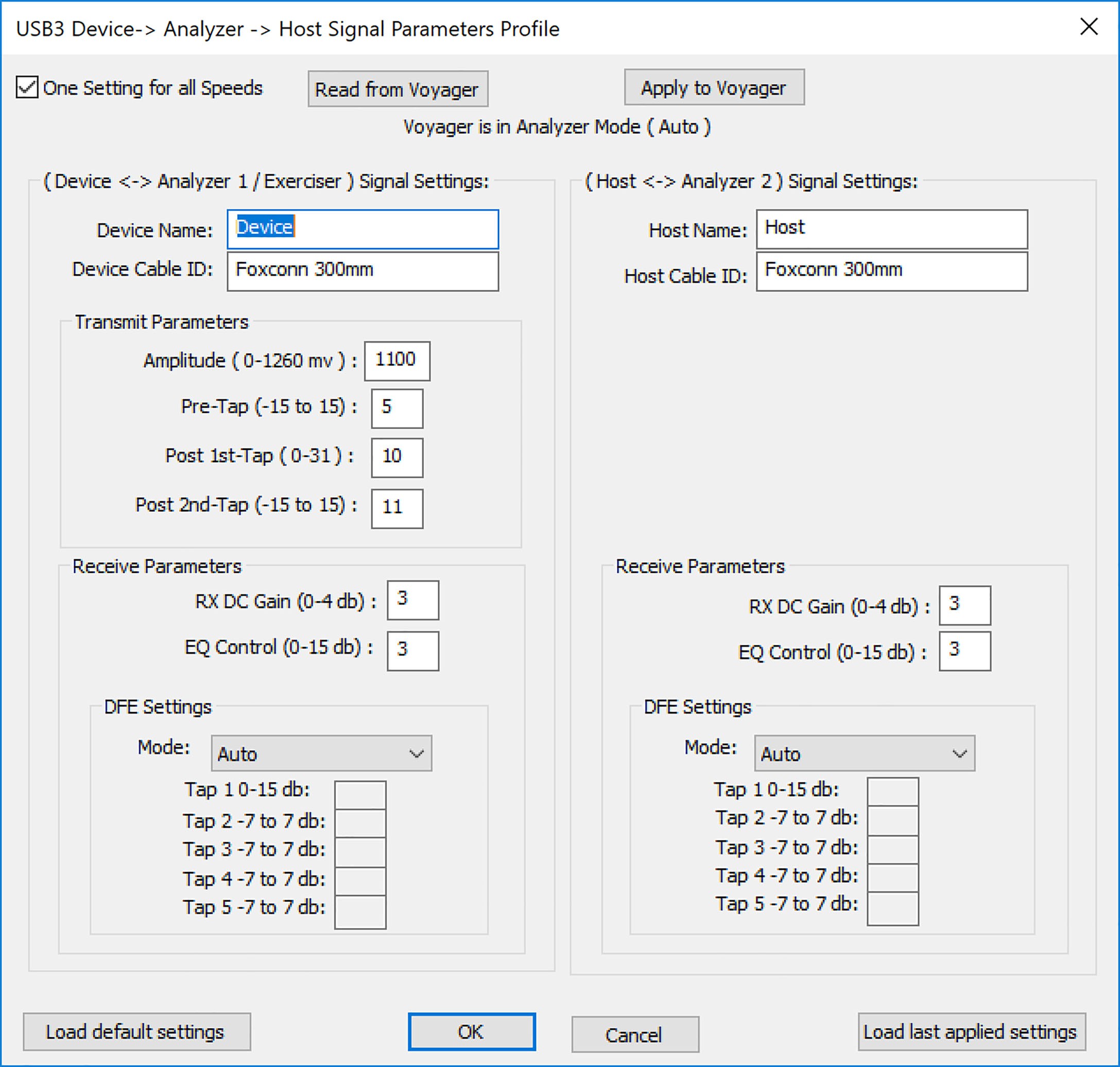
Use this window to:
-
Read from [analyzer]
-
Apply to [analyzer]
-
Enter Device to analyzer Signal Settings and Host to analyzer Signal Settings:
-
Device Name
-
Device Cable ID
-
Host Name
-
Host Cable ID
-
Transmit Parameters
-
Amplitude (0 to 1260mv)
-
Pre-Tap (-15 to +15)
-
Post 1st-Tap (0 to 31)
-
Post 2nd-Tap (-15 to 15)
-
-
Receive Parameters
-
RX DC Gain (0 to 4db)
-
EQ Control (0 to 15db)
-
-
DFE Settings
-
Mode: Auto, Off, Manual, Triggered Adaptation, Continuous Adaptation
-
If in Manual Mode, you can set different tap values:
-
Tap 1 0 to 15 db
-
Tap 2 -7 to 7 db
-
Tap 3 -7 to 7 db
-
Tap 4 -7 to 7 db
-
Tap 5 -7 to 7 db
-
-
You can also Load default settings or Load last applied settings.
Voyager M3x
To edit the Host Signal Parameters of a specific Profile entry, double-click the entry. The Host Signal Parameters Profile window opens.
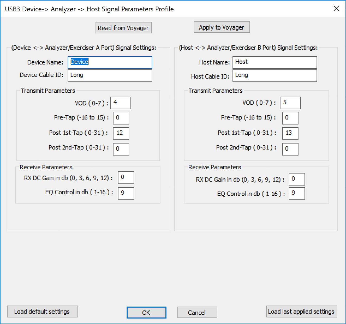
Use this window to:
-
Read from [analyzer]
-
Apply to [analyzer]
-
Enter Device to analyzer Signal Settings and Host to analyzer Signal Settings:
-
Device Name
-
Device Cable ID
-
Host Name
-
Host Cable ID
-
Transmit Parameters
-
VOD (0 to 7)
-
Pre-Tap (-16 to 15)
-
Post 1st-Tap (0 to 31)
-
Post 2nd-Tap (0 to 31)
-
-
Receive Parameters
-
RX DC Gain in db (0, 3, 6, 9, 12)
-
EQ Control in db (0 to 1)
-
-
You can also Load the default settings or Load the last applied settings.
Voyager M310P
To edit the Host Signal Parameters Profile of a specific entry, double click on the entry. The Host Signal Parameters Profile window opens.
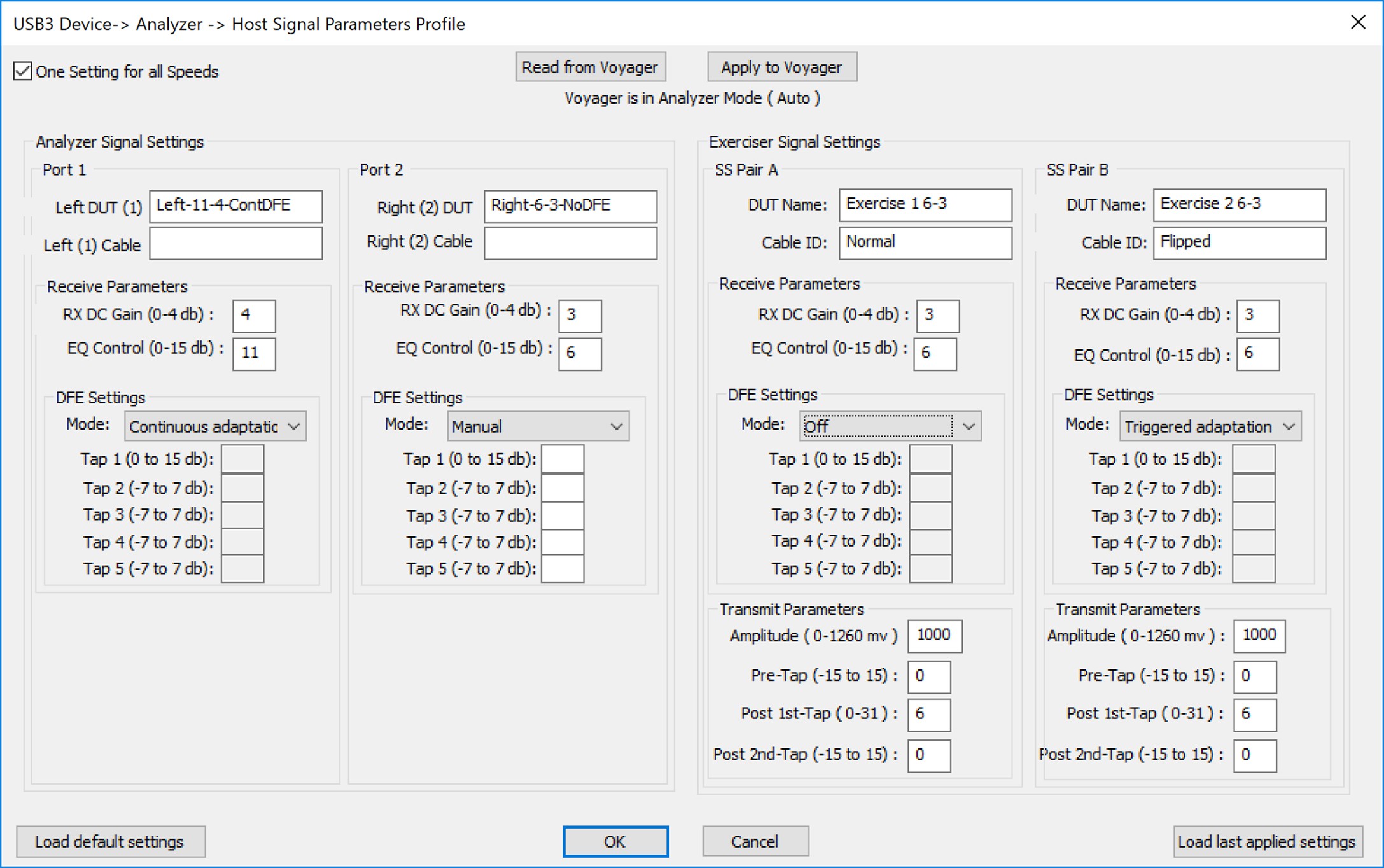
Use this window to:
-
Read from [analyzer]
-
Apply to [analyzer]
-
Enter analyzer Signal Settings for Port 1 and Port 2:
-
Left DUT (1) name
-
Right (2) DUT name
-
Left (1) Cable name
-
Right (2) Cable name
-
Receive Parameters
-
RX DC Gain (0 - 4 db)
-
EQ Control (0 - 15 db)
-
-
-
DFE Settings
-
Mode: Auto, Off, Manual, Triggered Adaptation, Continuous Adaptation
-
If in Manual Mode you can set the different tap values:
-
Tap 1 0 to 15 db
-
Tap 2 -7 to 7 db
-
Tap 3 -7 to 7 db
-
Tap 4 -7 to 7 db
-
Tap 5 -7 to 7 db
-
-
You can enter Exerciser Signal Settings for SS Pair A and SS Pair B:
-
DUT name
-
Cable ID
-
DUT name
-
Cable ID
-
Receiver Parameters
-
RX DC Gain (0 to 4 db)
-
EQ Control (0 to 15 db)
-
-
DFE Settings
-
Mode: Auto, Off, Manual, Triggered Adaptation, Continuous Adaptation
-
If in Manual Mode you can set the different tap values:
-
Tap 1 0 to 15 db
-
Tap 2 -7 to 7 db
-
Tap 3 -7 to 7 db
-
Tap 4 -7 to 7 db
-
Tap 5 -7 to 7 db
-
-
-
Transmit Parameters
-
Amplitude (0 to 1260mv)
-
Pre-Tap (-15 to +15)
-
Post 1st-Tap (0 to 31)
-
Post 2nd-Tap (-15 to 15)
-
You can also Load the default settings or Load the last applied settings.
Voyager M310e
To edit the Host Signal Parameters Profile of a specific profile, double click on the entry. The Host Signal Parameters Profile window appears.
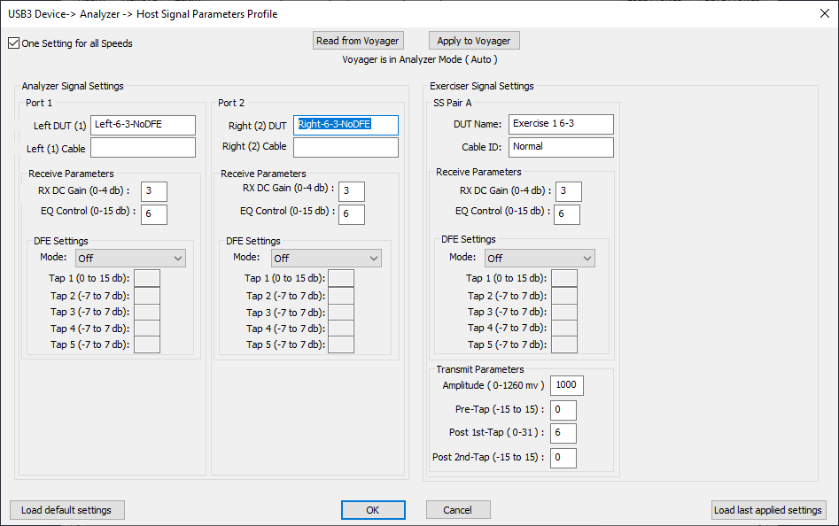
Use this window to:
-
Read from [analyzer]
-
Apply to [analyzer]
-
Enter analyzer Signal Settings for Port 1 and Port 2:
-
Left DUT (1) [name]
-
Right (2) DUT [name]
-
Left (1) Cable [name]
-
Right (2) Cable [name]
-
Receive Parameters
-
RX DC Gain (0 to 4 db)
-
EQ Control (0 to 15 db)
-
-
-
DFE Settings
-
Mode: Auto, Off, Manual, Triggered Adaptation, Continuous Adaptation
-
If in Manual Mode you can set the different tap values:
-
Tap 1 0 to 15 db
-
Tap 2 -7 to 7 db
-
Tap 3 -7 to 7 db
-
Tap 4 -7 to 7 db
-
Tap 5 -7 to 7 db
-
-
You can enter Exerciser Signal Settings for SS Pair A:
-
DUT name
-
Cable ID
-
DUT name
-
Cable ID
-
Receiver Parameters
-
RX DC Gain (0 to 4 db)
-
EQ Control (0 to15 db)
-
-
DFE Settings
-
Mode: Auto, Off, Manual, Triggered Adaptation, Continuous Adaptation
-
If in Manual Mode you can set the different tap values:
-
Tap 1 0 - 15 db
-
Tap 2 -7 to 7 db
-
Tap 3 -7 to 7 db
-
Tap 4 -7 to 7 db
-
Tap 5 -7 to 7 db
-
-
-
Transmit Parameters
-
Amplitude (0 to 1260mv)
-
Pre-Tap (-15 to +15)
-
Post 1st-Tap (0 to 31)
-
Post 2nd-Tap (-15 to 15)
-
You can also Load the default settings or Load the last applied settings.
Advisor T3
For the Advisor T3, to add, remove, edit, load (from a comma-delimited .csv file), or save (as a comma-delimited .csv file) USB 3.2 devices and to calibrate USB 3.2 connections:
-
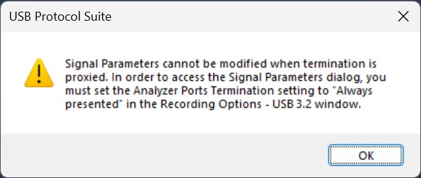
Select Setup > USB 3.2 Device/Signal Parameters. If the Advisor T3 is in default mode (Proxied from other port), the following message appears.
-
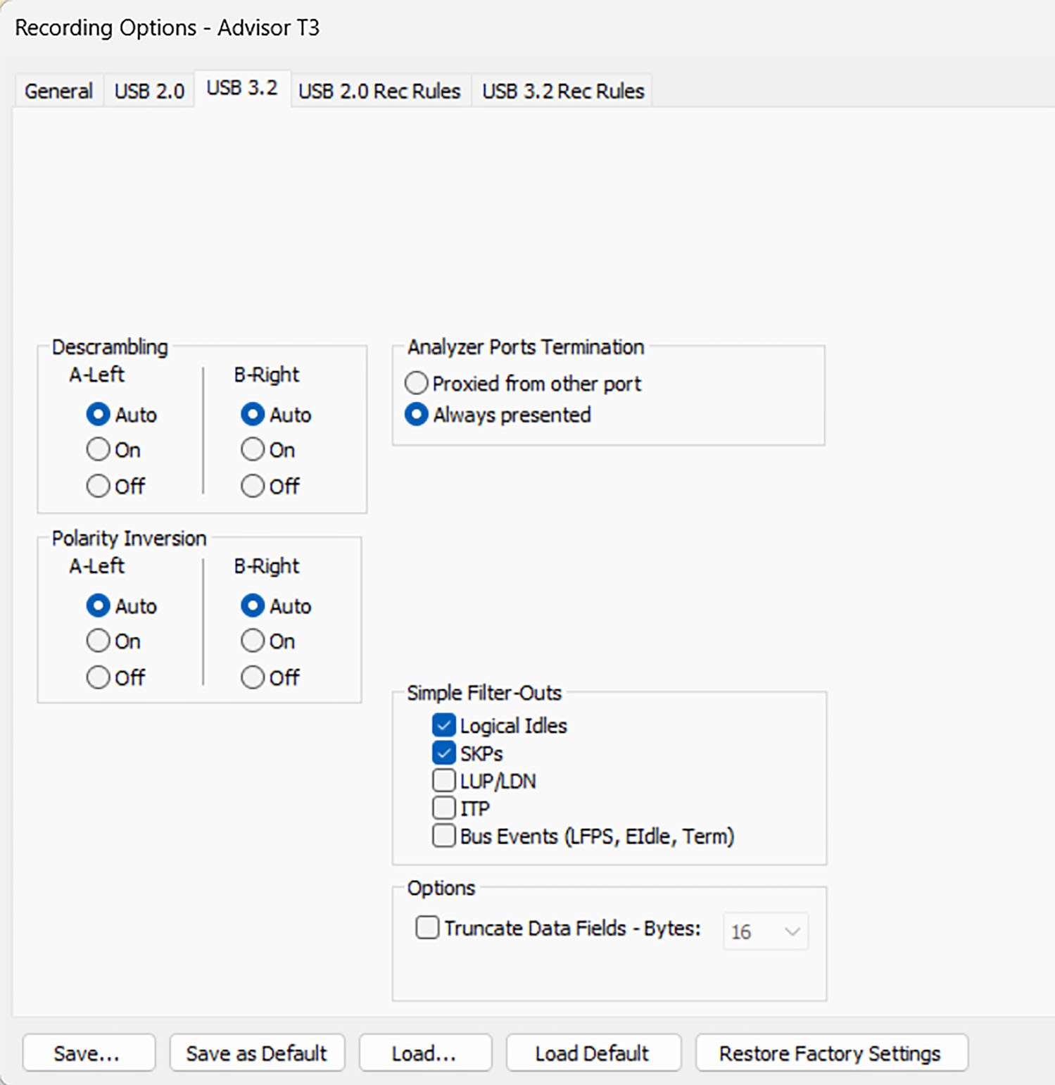
To set the Recording Options to Always presented, Open the USB Protocol Suite and select Recording Options.
-
Select General > Advisor T3.
-
Select the USB 3.2 tab.
-
Click the Always presented radio button.
-
-
This allows you to bring up the Host Signal Profiles for the Advisor T3.
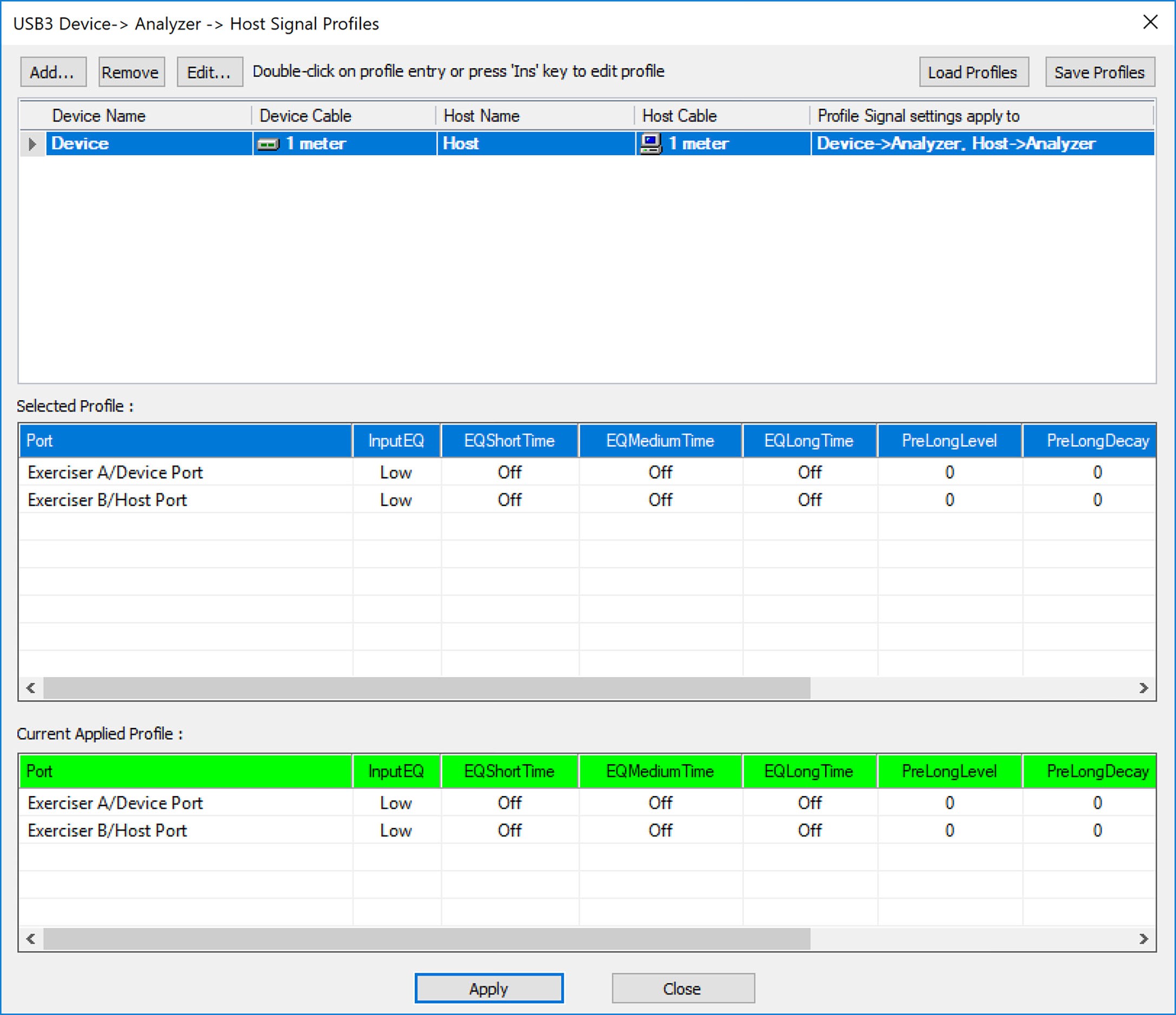
-
Double-click an existing profile to update its parameters.
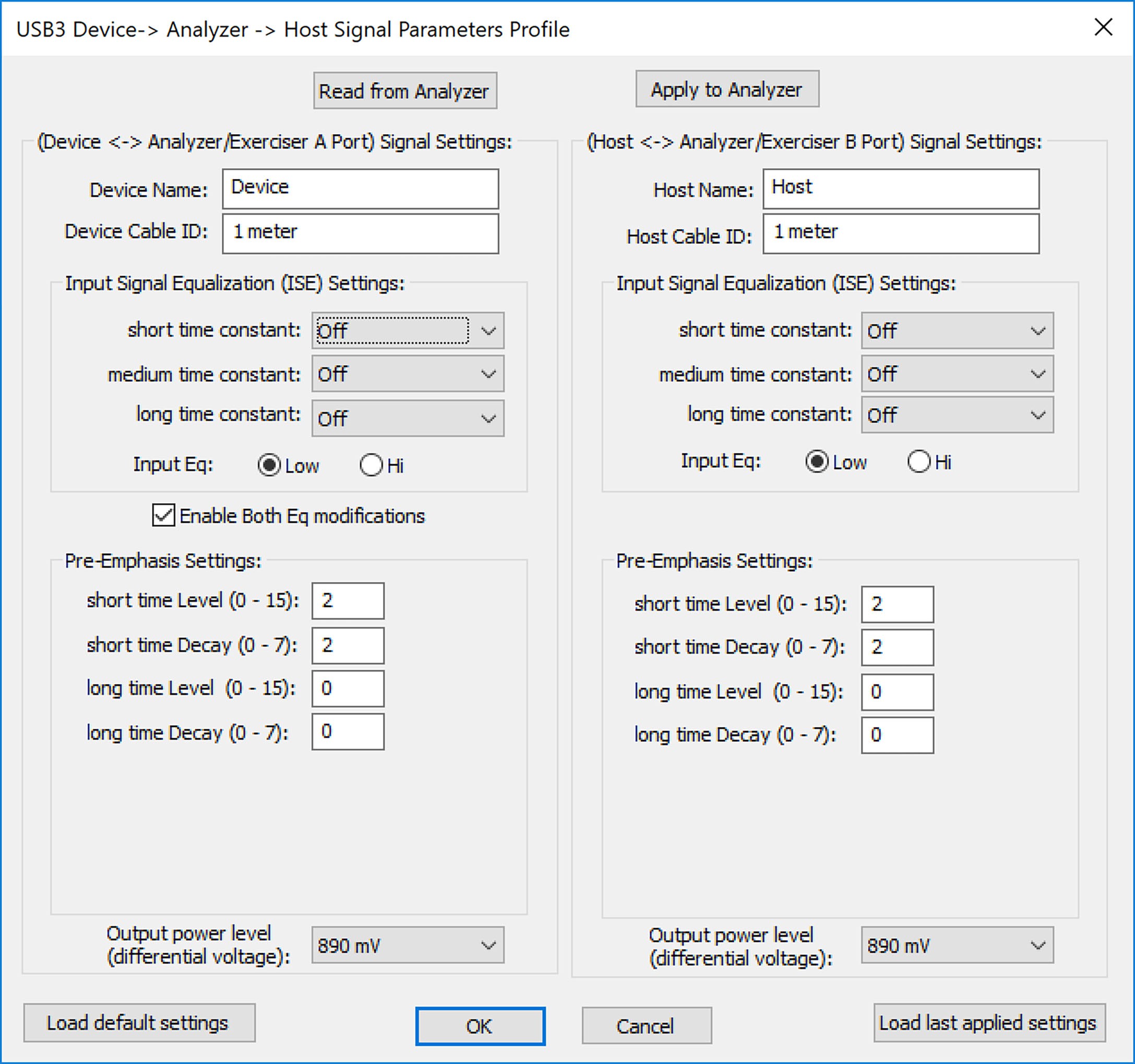
Use this window to:
-
Read from analyzer and Apply to analyzer
-
Enter Device to analyzer Signal Settings and Host to analyzer Signal Settings:
-
Device Name
-
Device Cable ID
-
Host Name
-
Host Cable ID
-
Input Signal Equalization (ISE) Settings
-
short time constant: Maximum, Moderate, Minimum, Off or Current
-
medium time constant: Maximum, Moderate, Minimum, Off or Current
-
long time constant: Maximum, Moderate, Minimum, Off or Current
-
-
-
If you select to Enable Both Equalization Modifiers you can set:
-
Input Equalization – Low or High as well as:
-
Pre-Emphasis Settings
-
short time Level (0 to 15)
-
short time Decay (0 to 7)
-
long time Level (0 to 15)
-
short time Decay (0 to 7)
-
-
-
Output power level (differential voltage): 405 - 890 mv You can also Load the default settings or Load the last applied settings.
-
USB 3.2 Cabling and Signal Integrity
The analyzer requires two connector discontinuities. In addition, bus-powered devices are susceptible to voltage drops on VBUS.
To maintain the best possible signal integrity for all devices under test, use high-quality cabling and use the shortest possible cable lengths. Do not “stress” the system by using long or low-quality cabling that might result in signal degradation.
If you suspect signal integrity problems in capture situations, you should first try using shorter and higher-quality cables to see if this rectifies the problem.