
Audio Expert System: aptX® 'hiccup' Detected
This paper presents a case study in Bluetooth® audio debugging that highlights the importance of Frontline's Audio Expert System (AES) in the process. The actual case involves transmission of a high quality, stereo audio using the aptX® codec from a smartphone to a Bluetooth headset. The transmission contained SBC encoded packets despite a successful negotiation of aptX® encoding and decoding mechanism between the source and the sink devices. Frontline's AES software discovered this transmission error which most likely would not have been easily discovered by using traditional Bluetooth protocol and event analysis. Without the Audio Expert System, a product may have been shipped that was not performing as expected by the manufacturer.
Background
In Bluetooth technology, Audio/Video Distribution Transport Protocol (AVDTP) uses Advanced Audio Distribution Profile (A2DP) for streaming audio in stereo. The A2DP encompasses compression techniques to reduce the amount of radio frequency bandwidth required to transmit audio. In addition to A2DP, Audio/Video Remote Control Profile (AVRCP) controls certain functions of the sending device such as pause, play, next track, etc.
All Bluetooth products using A2DP are required to implement audio encoding and decoding using low complexity Sub Band Coding (SBC) that supports up to 345 kb per second bit rate for stereo audio. The SBC codec has some issues though. SBC coding and decoding produces some undesirable artifacts in the audio signal. In addition, the SBC encoding and decoding cycle introduces a time lag in the audio. To improve on SBC's artifacts and time lag issues, a CSR proprietary codec that is called aptX® is implemented on some Bluetooth products.
During the negotiation phase, both Bluetooth devices handshake and they automatically discover the best codec and the highest bit rate to use for audio. If both devices support aptX®, it is used rather than the default SBC.
The AES software helps identify audio issues in Bluetooth protocol by highlighting information, warnings, and errors related to audio data, codec used, and Bluetooth protocol implementation. They are collectively called “events” in AES. The AES window shows audio data plotted as PCM samples versus time in the Wave Panel. The audio data, codec, and protocol events are also graphically displayed in the Wave Panel, and with a single click on an event, engineers and testers are brought directly to the exact packets or frames related to the event in the Bluetooth protocol trace in the Main windows. This helps users find issues quickly and easily. The events are shown time-aligned with both the actual audio waveform and bit rate variances graph in the Wave Panel. The bit rate variance graph shows the average or actual amount of Bluetooth audio data sent over a period of time.
AES can operate in two modes: 1) referenced mode, and 2) non-referenced mode. In referenced mode a Frontline provided audio test file is streamed between the Devices Under Test (DUTs). The test file content and parameters are known to the AES software that performs a comparison for deviations. This process helps the software accurately detect anomalies created by the streaming process. In non-referenced mode DUTs stream audio of unknown content, limiting the types of detectable events. The software automatically determines the operation mode with no user input required.
Test Setup
The following DUTs below were used in our test setup:
-
DUT1 = smartphone with Bluetooth and aptX® capability. The smartphone operating system was Android.
-
DUT2 = Earphones with Bluetooth and aptX® capability.
-
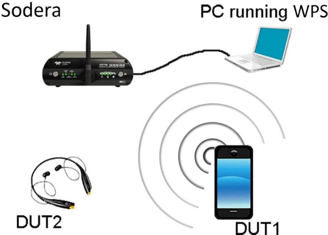
The protocol analyzer: Frontline Sodera Dual Mode Bluetooth Protocol Analyzer with Bluetooth Audio Expert System activated. The Sodera is connected to a personal computer (PC) that is running Wireless Protocol Suite software.
DUT1 was used as a source device. DUT1 was streaming an AES Reference file.
DUT2 was used as a sink device. After establishing a valid Bluetooth link, DUT2 played the AES Reference file.
The audio test file was played from the Bluetooth smart phone to the Bluetooth headphone. The data captured by the Frontline Sodera hardware was sent to the analysis computer running Wireless Protocol Suite software with AES. As the data was captured, it was analyzed by the AES module and displayed live in the AES window. The AES software automatically detected the test ID tones in the captured audio and operated in the referenced mode. The figure below shows the test setup.
Discussion
The test began without any issue. DUT1 and DUT2 negotiated a Bluetooth connection suitable for transmitting the audio. When the Reference Audio was played there were no obvious audio distortions or anomalies heard by the tester.
The tester used a Frontline Sodera configured for capturing Classic Bluetooth over a single connection.
In the Main window’s AVDTP Signaling tab, we see the start of the negotiation between DUT1 and DUT2 to establish an audio connection (see Figure below). At frames 554 and 602, the initiating or local device sends an AVDTP_DISCOVER command. The remote device responds by identifying the ACP Stream Endpoint IDs. In this case the remote device identifies three audio media-type devices that are SNK (sink) devices currently not in use: SEPID (Stream Endpoint Identification) 1 through 10.
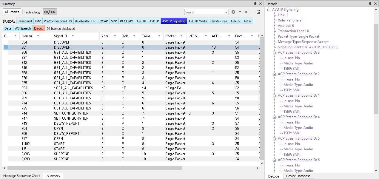
"ACP" is AVDTP terminology for the remote device.
The next step in the negotiation is to get the audio capabilities of each SEPID. For each SEPID there is an exchange of GET_CAPABILITIES AVDTP signals.
Examination of the Main windows AVDTP Signaling protocol tab shows, at frame 602, the peripheral device requested SEP (Stream End Point) characteristics from SEPID (SEP Identifier) 3. Details of the GET_CAPABILITIES command are shown below.
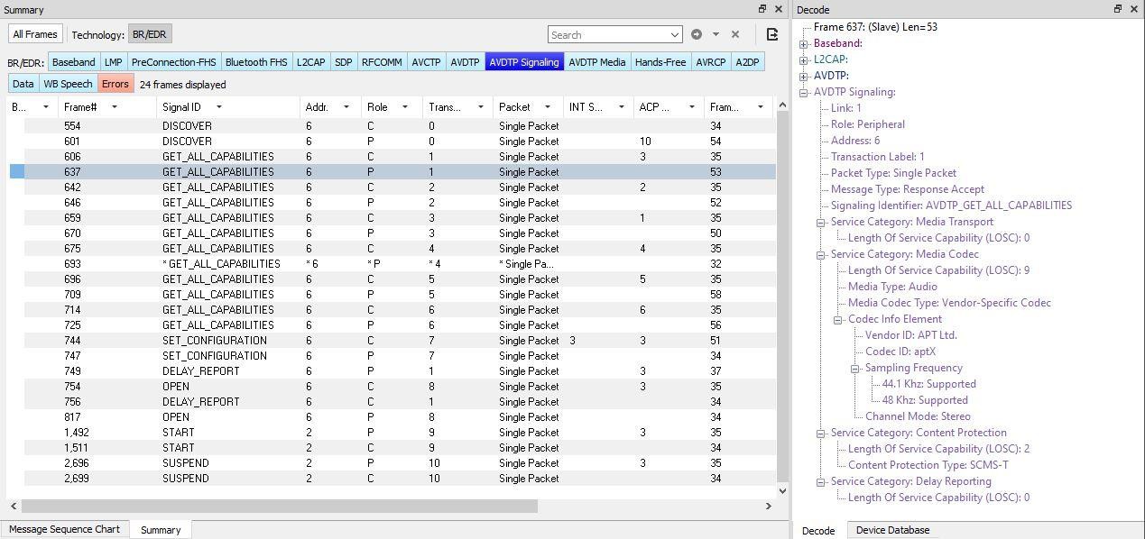
At frame 774, the remote device responds to the GET_CAPABILITIES for SEPID 3, reporting that this SEP codec is aptX® with a Channel Mode of Stereo.
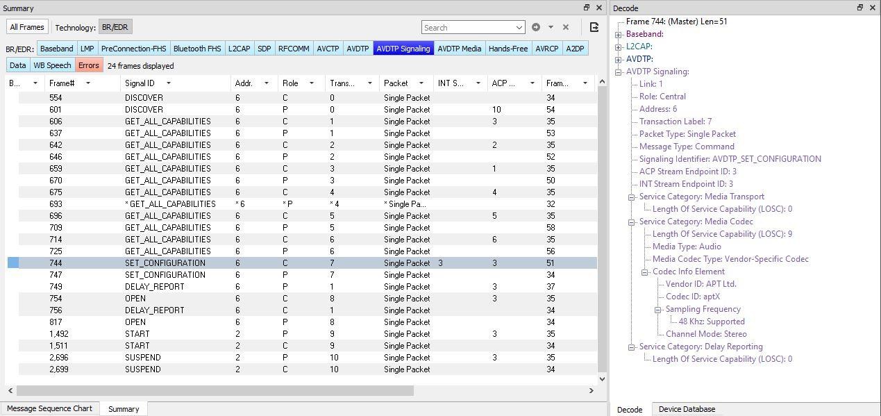
In the Figure above, frames 606 through 725 perform the GET_CAPABILITIES negotiation between the local and remove device for SEPIDs 1 through 6.
Frames 744 and 747 set the specific details of the connection with the SET_CONFIGURATION signal. The local device sets the remote endpoint to the aptX® device (ACP Stream Endpoint ID: 3). The Codec, Sampling Frequency and Channel Mode are also configured.
Frames 754 and 817 are the local request and the remote response to OPEN the audio stream.
Frames 1,492 and 1,511 START the audio stream with the local request and remote response respectively.
So far, the process of setting up an aptX® audio connection between DUT1 and DUT2 appears normal, correct and error free. We now move from the AVDTP protocol to the A2DP protocol to observe the audio.
Problem Discovery
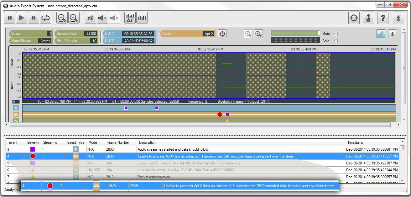
In the Wireless Protocol Suite software, the audio data is shown in the A2DP tab in the Main windows, which is the first audio frame, is identified as being aptX® encoded because of the successful codec negotiation. At this frame, the conventional audio data analysis methods do not show any issues. Assuming the data is aptX® encoded, the AES software passes it to the AES aptX® decoder. However, the data was not decoded correctly and is marked as a bad aptX® frame. On further analysis, the AES software discovers that the frame is not aptX® encoded but is actually SBC encoded. Frame 2839 begins with “0x9C”, and all SBC audio frames begin with sync word “0x9c” as shown in E.1.3. The AES cannot solely rely on the sync word to determine if it is an SBC frame. To confirm the suspicion, the AES passed the data through its SBC decoder, and the data came out cleanly decoded.
The AES software not only showed that there is a problem in the audio data but also made it clear where the problem is.
The Error that is identified by Event 4, the Severity red circle 

Conclusions
This case shows the value of Frontline's Audio Expert System. An error in the transmission of an audio stream compressed using aptX® was not easily detected in the protocol analysis using frames. While, in this situation with audio streaming between a smartphone and a Bluetooth headset, there was not a significant disruption of the audio, but in playback using other devices there may have been a more significant interruption of the audio streaming.
The smartphone manufacturer may wish to find out why aptX® compressed audio contained SBC compressed data in the stream. We can speculate that there may be an underlying problem with clearing stacks or memory between streaming events. This investigation is beyond the scope of this paper.
Getting the Android Link Key for Classic Decryption
Bluetooth devices on an encrypted link share a common “link key” used to exchange encrypted data. For a Bluetooth sniffer, such as the Frontline X500e, to be able to decrypt the encrypted data, it must also have this shared link key. For obvious security reasons, the link key is never sent over the air, so either the user must get the key out of one of the devices being sniffed and supply the key to the sniffer or the sniffer must create the key itself.
Bluetooth devices using the Android operating system have a "developer" option that will provide the link key for Classic Bluetooth decryption This procedure will use the developer options to obtain the Android HCI (Host Controller Interface) log that contains the link keys for all active links.
What You Need to Get the Android Link Key
The process applies to the Android 4.4 or later operating system.
-
Android device with Bluetooth enabled and paired with another Bluetooth device.
-
Wireless Protocol Suite software installed on your computer.
-
Android Debug Bridge (optional)
Each Android device model can vary in screen organization, layout, and format. The directions in this paper are based on a known typical Android device. Refer to the manufacturer's manual, on-line help, or technical support for detailed information about your particular device.
Activating Developer options
The Android HCI log will contain the link key for an active Bluetooth link.
-
On the Android device, go to Settings.
-
Select About.
-
In the About screen, tap on Build number eight times. At some point you will see a notice like "You are now a developer!".
On some devices, the build information may be under one or more sub-screens below the About screen. Also, the number of taps may vary. In most cases the screen will provide status of your tap count.
-
Return to the Settings screen and you will see Developer options.
Retrieving the HCI Log
Now that Developer options have been activated on the Android device, you can retrieve the HCI log.
-
On the Android device go to Settings.
-
Select Developer options.
-
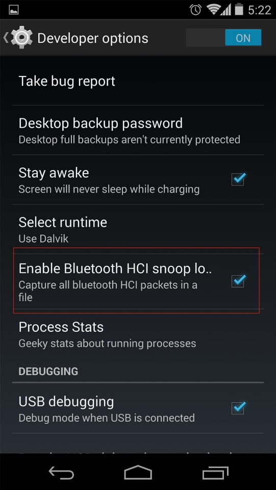
Click to enable Bluetooth HCI snoop logging.
-
Return to the Settings screen and select Developer options.
-
In the Developer options screen, select Enable Bluetooth HCI snoop log. The log file is now enabled.
-
On the Android device, turn off Bluetooth.
-
Turn on Bluetooth.
-
Reboot the Android device.
The HCI log file is now being generated and is saved to /sdcard/btsnoop_hci.log.
Samsung devices have a slightly different location for the btsnoop file.
There are two options for retrieving the HCI log from the Android device.
-
Attach the Android device to your computer. The file /sdcard/btsnoop_hci.log is in the root of one of the mountable drives. Copy the file to directory C:/Users/Public/Public Documents/Frontline Test Equipement/My Capture File/.
*For macOS installations, the Wireless Protocol Suite directory locations are available via a link that is created in the Documents shortcut in your Finder window within a “Teledyne LeCroy Wireless” folder.
-
The second option is to use the Android Debug Bridge (ADB) using the following steps. The debug bridge is included with Android Software Developer Kit.
a. On the Android device Development screen, select Android debugging or USB debugging.
b. Connect your computer and Android device with a USB cable.
c. Open a terminal on your computer and run the following command: adb devices.
d. Your Android device should show up in this list confirming that ADB is working.
List of devices attached XXXXXXXXXXX device
-
In the terminal enter the following command to copy the HCI Log to your computer.
adb pull /sdcard/btsnoop_hci.log
Using the Wireless Protocol Suite software to Get the Link Key
You will load the HCI Log file btsnoop_HCI.log into the Wireless Protocol Suite software on your computer as a capture file. Then you can use the Main windows to locate the link key.
-
Open the Wireless Protocol Suite software.
-
From the main menu select File, Open....
-
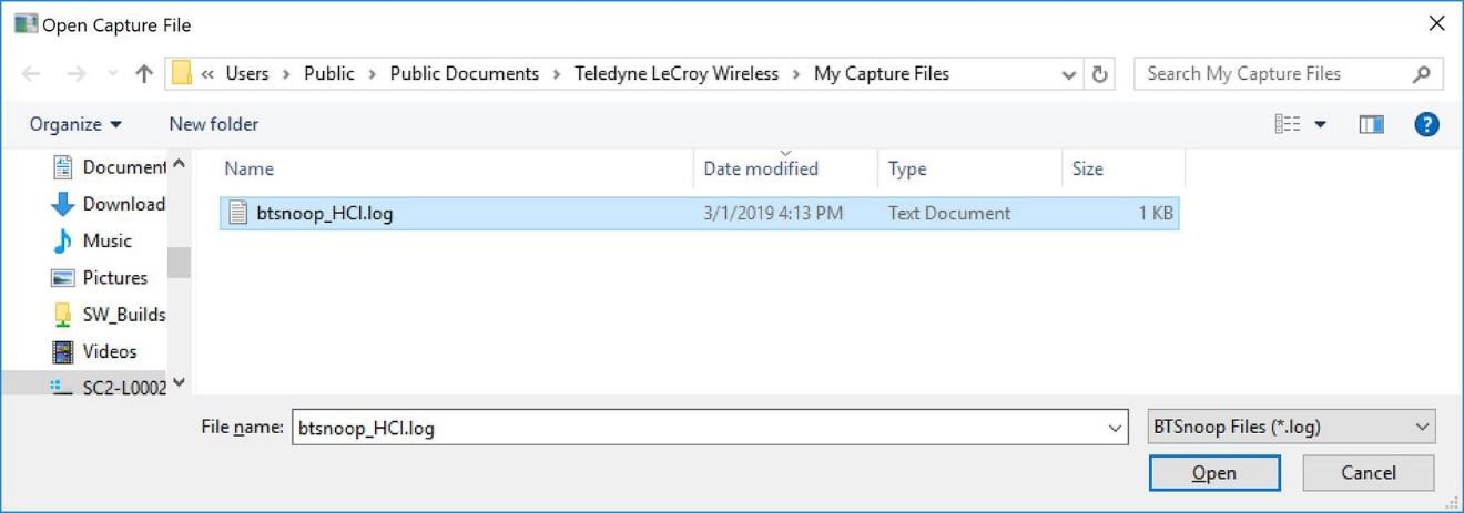
When the Open Capture File window appears, set the file type to BTSnoop Files (*.log). If not already selected, navigate to the My Capture Files directory and select btsnoop_hci.log.
-
Open the Main window.
-
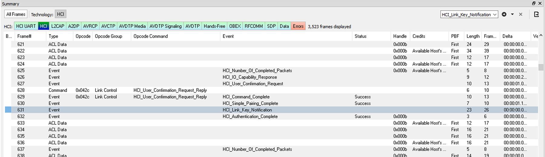
In the Summary pane protocol tabs, select HCI. (See image below)
-
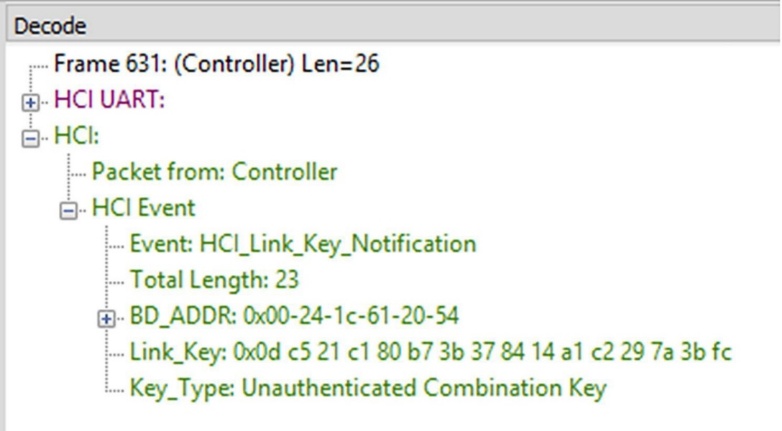
Using the Search box located in the Summary pane, search for an “HCI_Link_Key_Notifcation” event in the capture. If not found, the key may also be found searching for “HCI_Link_Key_Request_Reply”.
-
Once the event is found, look in the Decode pane under the “HCI” section for a field named “Link_Key”. The value found is the Link Key, which can be copied and pasted into the Security pane.
Decrypting Encrypted Bluetooth® Low Energy
How Encryption Works in Bluetooth® Low Energy
Data encryption is used to prevent passive and active—man-in-the-middle (MITM) — eavesdropping attacks on a Bluetooth Low Energy link. Encryption is the means to make the data unintelligible to all but the Bluetooth central and peripheral devices forming a link. Eavesdropping attacks are directed on the over-the-air transmissions between the Bluetooth Low Energy devices, so data encryption is accomplished prior to transmission using a shared, secret key.
Bluetooth® Low Energy Security
"Paris is quiet and the good citizens are content." Upon seizing power in 1799 Napoleon sent this message on Claude Chappe’s optical telegraph. Chappe had invented a means of sending messages line-of- sight. The stations were placed approximately six miles apart and each station had a signaling device made of paddles on the ends of a rotating “regulator” arm whose positions represented code numbers. Each station was also outfitted with two telescopes for viewing the other stations in the link, and clocks were used to synchronize the stations. By 1803 a communications network extended from Paris across the countryside and into Belgium and Italy.
Chappe developed several coding schemes throughout the next few years. The station operators only knew the codes, not what characters they represented. Not only was Chappe’s telegraph system the first working network with protocols, synchronization of serial transmissions, but it also used data encryption. Although cryptography has been around for millenniums—dating back to 2000 B.C. — Chappe, was the first to use it in a wide area network in the modern sense.
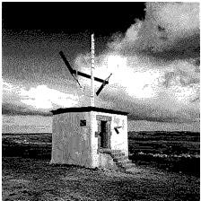
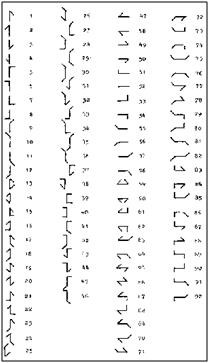
Of course, anyone positioned between the telegraph stations that had Chappe's telegraph code in hand could decode the transmission. So, securing the code was of paramount importance in Chappe's protocol.
Modern wireless networks such as Bluetooth Low Energy employ security measures to prevent similar potentially man-in-the- middle attacks that may have malicious intent.
Bluetooth Low Energy devices connected in a link can pass sensitive data by setting up a secure encrypted link. The process is similar but not identical to Bluetooth BR/EDR Secure Simple Pairing. One difference is that in Bluetooth Low Energy, the confidential payload includes a Message Identification Code (MIC) that is encrypted with the data. In Bluetooth BR/EDR, only the data is encrypted. Also, in Bluetooth Low Energy the secure link is more vulnerable to passive eavesdropping, however because of the short transmission periods this vulnerability is considered a low risk. The similarity to BR/EDR occurs with "shared secret key", a fundamental building block of modern wireless network security.
This paper describes the process of establishing a Bluetooth Low Energy secure link.
Pairing
A Bluetooth Low Energy device that wants to share secure data with another device must first pair with that device. The Security Manager Protocol (SMP) carries out the pairing in three phases.
-
The two connected Bluetooth Low Energy devices announce their input and output capabilities and from that information, determine a suitable method for phase 2.
-
The purpose of this phase is to generate the Short Term Key (STK) used in the third phase to secure key distribution. The devices agree on a Temporary Key (TK) that, along with some random numbers, creates the STK.
-
In this phase, each device may distribute to the other device up to three keys.
-
the Long Term Key (LTK) used for Link Layer encryption and authentication,
-
the Connection Signature Resolving Key (CSRK) used for data signing at the ATT layer, and
-
the Identity Resolving Key (IRK) used to generate a private address.
-
The LTK is the primary interest in this paper. CSRK and IRK are covered briefly at the end.
Bluetooth Low Energy uses the same pairing process as Classic Bluetooth: Secure Simple Pairing (SSP). During SSP initially each device determines its capability for input and output (IO). The input can be None, Yes/No, or Keyboard with Keyboard having the ability to input a number. The output can be either None or Display with Display having the ability to display a 6-digit number. For each device in a paring link the IO capability determines their ability to create encryption shared secret keys.
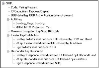
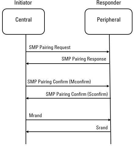
The Pairing Request message is transmitted from the initiator containing the IO capabilities, authentication data availability, authentication requirements, key size requirements, and other data. A Pairing Response message is transmitted from the responder and contains much of the same information as the initiator's Pairing Request message thus confirming that a pairing is successfully negotiated.
In the sample SMP decode, in the figure at the right, note the “keys” identified. Creating a shared, secret key is an evolutionary process that involves several intermediary keys. The resulting keys include:
-
IRK: 128-bit key used to generate and resolve random address.
-
CSRK: 128-bit key used to sign data and verify signatures on the receiving device.
-
LTK: 128-bit key used to generate the session key for an encrypted connection.
-
Encrypted Diversifier (EDIV): 16-bit stored value used to identify the LTK. A new EDIV is generated each time a new LTK is distributed.
-
Random Number (RAND): 64-bit stored value used to identify the LTK. A new RAND is generated each time a unique LTK is distributed.
Of particular importance to decrypting the encrypted data on a Bluetooth Low Energy link is LTK, EDIV, and RAND.
Pairing Methods
The two devices in the link use the IO capabilities from Pairing Request and Pairing Response packet data to determine which of two pairing methods to use for generation of the Temporary Key (TK). The two methods are Just Works and Passkey Entry1. An example of when Just Works method is appropriate is when the IO capability input = None and output = None. An example of when Passkey Entry would be appropriate would be if input= Keyboard and output = Display. There are 25 combinations that result in 13 Just Works methods and 12 Passkey Entry methods.
In Just Works, the TK = 0. In the Passkey Entry method,

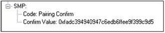
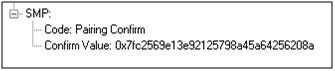
The initiating device will generate a 128-bit random number that is combined with TK, the Pairing Request command, the Pairing Response command, the initiating device address and address type, and the responding device address and address type. The resulting value is a random number Mconfirm that is sent to the responding device by the Pairing Confirm command. The responding device will validate the responding device data in the Pairing Confirm command and if it is correct will generate a Sconfirm value using the same methods as used to generate Mconfirm only with different 128-bit random number and TK. The responding device will send a Pairing Confirm command to the initiator and if accepted, the authentication process is complete. The random number in the Mconfirm and Sconfirm data is Mrand and Srand respectively. Mrand and Srand have a key role in setting encrypting the link.
Finally, the central and peripheral devices exchange Mrand and Srand so that the central can calculate and verify Mconfirm and the peripheral can likewise calculate and verify Sconfirm.
A third method, Out Of Band (OOB), performs the same as Pass Key, but through another external link.
Encrypting the Link
The Short Term Key (STK) is used for encrypting the link the first time the two devices pair. STK remains in each device on the link and is not transmitted between devices. STK is formed by combining Mrand and Srand which were formed using device information and TKs exchanged with Pairing Confirmation (Pairing Confirm).
Encryption Key Generation and Distribution
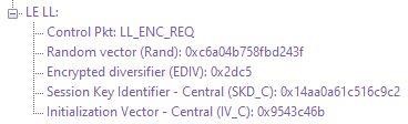
To distribute the LTK, EDIV, and Rand values, an encrypted session needs to be set up. The initiator will use STK to enable encryption on the link. Once an encrypted link is set up, the LTK is distributed. LTK is a 128-bit random number that the central device will generate along with EDIV and Rand. Both the central and peripheral devices can distribute these numbers, but Bluetooth Low Energy is designed to conserve energy, so the central device is often resource constrained and does not have the database storage resources for holding LTKs. Therefore, the central will distribute LTK, EDIV, and Rand to the peripheral device for storage. When a central begins a new encrypted session with a previously linked peripheral device, it will request distribution of EDIV and Rand and will regenerate LTK.
Encrypting Data Transmission
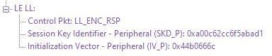
Data encryption begins with encrypting the link. The Session Key (SK) is created using a session key diversifier (SKD). The first step in creating an SK is for the central device to send Link Layer encryption request message (LL_ ENC_REQ) that contains the SKDcentral. The SKDcentral is generated using the LTK. The peripheral receives SKDcentral, generates SKDperipheral, and generates SK by concatenating parts of SKDcentral and SKDperipheral. The peripheral device responds with an encryption response message (LL_ENC_RSP) that contains SKDcentral; the central will create the same SK.
Now that an SK has been calculated, the central and peripheral devices will now begin a handshake process. The central will transmit unencrypted LL_START_ENC_REQ, but sets the peripheral to receive encrypted data using the recently calculated SK. The peripheral responds with encrypted LL_START_ENC_RSP that uses the same SK just calculated and setting the peripheral to receive encrypted data. Once the central receives the peripheral’s encrypted LL_ START_ENC_RSP message and responds with an encrypted LL_START_ENC_RSP message the Bluetooth Low Energy devices can now begin transmitting and receiving encrypted data.
IRK and CSRK Revisited
Earlier in this paper it was stated that LTK would be the focus, however the IRK and CSRK were mentioned. We revisit these keys because they are used in situations that require a lesser level of security. First, note that IRK and CSRK are passed in an encrypted link along with LTK and EDIV.
Use of the IRK and CSRK attempt to place an identity on devices operating in a piconet. The probability that two devices will have the same IRK and generate the same random number is low, but not absolute.
IRK and Bluetooth Low Energy Privacy Feature
Bluetooth Low Energy has a feature that reduces the ability of an attacker to track a device over a long period buy frequently and randomly changing an advertising device's address. This is the privacy feature. This feature is not used in the discovery mode and procedures but is used in the connection mode and procedures.
If the advertising device was previously discovered and has returned to an advertising state, the device must be identifiable by trusted devices in future connections without going through the discovery procedure again. The IRK stored in the trusted device will overcome the problem of maintaining privacy while saving discovery computational load and connection time. The advertising device’s IRK was passed to the central device during initial bonding. The central device will use the IRK to identify the advertiser as a trusted device.
CSRK and Signing for Authentication
Bluetooth Low Energy supports the ability to authenticate data sent over an unencrypted ATT bearer between two devices in a trust relationship. If authenticated pairing has occurred and encryption is not required (security mode 2), data signing is used if CSRK has been exchanged. The sending device attaches a digital signature after the data in the packet that includes a counter and a message authentication code (MAC). The key used to generate MAC is CSRK. Each peer device in a piconet will have a unique CSRK.
The receiving device will authenticate the message from the trusted sending device using the CSRK exchanged from the sending device. The counter is initialized to zero when the CSRK is generated and is incremented with each message signed with a given CSRK. The combination of the CSRK and counter mitigates replay attacks.
Table of Acronyms
|
CSRK |
Connection Signature Resolving Key |
|
EDIV |
Encrypted Diversifier |
|
IO |
Input and output |
|
IRK |
Identity Resolving Key |
|
LTK |
Long Term Key |
|
Mconfirm |
128-bit confirm value from initiator |
|
MIC |
Message Integrity Check |
|
MITM |
Man-in-the-middle |
|
Mrand |
128-bit random number used to generate Mconfirm |
|
OOB |
Out of Band |
|
RAND |
Random Number |
|
Sconfirm |
128-bit confirmation value from the responder |
|
SK |
Session key |
|
SMP |
Security Manager Protocol |
|
Srand |
128-bit random number used to generate Sconfirm |
|
SSP |
Secure Simple Pairing |
|
STK |
Short Term Key |
|
TK |
Temporary Key |