
Whether you create a traffic generation from scratch or use the Export command, there are a few rules about the format of the generation file that you should review. These are presented in this section.
Traffic is generated from a text file named *.utg. Within the text file:
-
The data format for data fields such as Pids and Raw bits is hex.
-
Each packet definition consists of this set of assignments: key=value.
-
White space is permitted around the equals sign.
-
There are no restrictions on dividing packet definition to lines nor is it necessary to define each packet in a separate line, although it is recommended.
-
The maximum number of characters in a line is 250.
-
The characters “#” and “;” indicate end-of-line comments (i.e., the rest of the line is ignored).
-
Comments are not allowed within brackets [ ].
-
No keys or values are case-sensitive.
Each packet definition starts with one of these assignments: pid=N (where N is a string representing a valid packet identifier or an eight bit value)
OR
frame=N (where N is an eleven bit value of the frame number or the strings auto and keep_alive).
A bus condition definition starts with one of these assignments:
-
reset=N (where N is a positive integer or string)
-
suspend=N (where N is a positive integer)
-
resume=N (where N is a positive integer)
-
chirp=here
Subsequent assignments after a packet starting assignment define the values of particular fields within the packet. If a field is not defined, it is assumed to be 0. Values are assumed to be decimal unless they are prefixed with 0x and then are interpreted as hexadecimal. Values within a data block assignment are always assumed to be hexadecimal and should not be prefixed by 0x.
Script Control of IntelliFrame vs Bitstream modes
To force the .utg file to run in IntelliFrame mode, add ;intelliframe=ON to the FIRST LINE of the .utg file.
To force the .utg file to run in Bitstream mode, add ;intelliframe=OFF to the FIRST LINE of the .utg file.
These commands are useful if an automated interface, such as the USB Compliance Suite, is running a script.
If you run the script manually, to allow selection of IntelliFrame or Bitstream mode from the toolbar, make sure the .utg file has no such Intelliframe command line.
Sample Syntax
; Start of Frames (SOF's)

chirp = HERE	; This is necessary for Hi Speed scenarios to establish running at Hi Speed

frame=auto idle=TO_EOF ; 1 empty frame, frame number generated automatically frame=23 idle=TO_EOF	; 1 empty frame, frame number is 23

empty_frames=73	; 73 empty frames, frame numbers generated automatically

; Tokens (always need Address and Endpoint) pid=SETUP addr=2 endp=3

pid=IN addr=1 endp=0 idle=TO_EOF

pid=IN addr=1 endp=0 CRC=0x1E idle=TO_EOF; Force a CRC value pid=OUT addr=1 endp=0 idle=368

pid=PING addr=1 endp=0 idle=368

; Split

pid=SPLIT hub_addr=5 sc=1 port=2 s=0 e=1 et=2

; Data pid=DATA0

data=(

23 03 08 00 01 00 00 00

)

idle=500 ; 8 bytes

; Link Power Management. These 2 must be consecutive pid=EXT addr=1 endp=0 idle=368

pid=LPM hird=1 link_state=1 remote_wake=0 idle=368
Key Codes
The following table contains available key codes and their definitions.
|
Key Code |
Format |
Description |
|
File Control Keys |
||
|
file_type |
UPAS CHIEF |
Must be included at the beginning of the file to determine the speed of packets to be generated. Value must be file_type=UPAS to allow for high speed traffic, IntelliFrame operation, expected_pid and device_pid key support. Full and low speed traffic, and Bitstream operation are supported on all file_type= values. If this statement does not appear in the file, the default is file_type=CHIEF, allowing backward compatibility with older USB Chief™ .usb files. |
|
file_version |
integer |
Must be included after the file_type= key to determine the version of this file. Value is currently 4. Usage: file_version=4 |
|
file_mode |
HOST DEVICE |
Sets generation mode to host or device. For generation to work, this must match the selection found in the Recording Options > Misc dialog. |
|
file_speed |
HIGH HI FULL LOW |
This must be included after the file_version= key to determine the speed of packets to be generated. Values are HIGH, HI, FULL, or LOW. Example: file_speed=FULL. Only one file_speed= is allowed per .utg file, but low speed traffic on a full speed bus can be created by adding the speed=LOW key to a low speed packet in a file defined as file_speed=FULL. No other mixing of speeds is allowed. HI is the same as HIGH and was added to conform to the USB terms. |
|
loop_count wrap_count |
0 through 16382 or “infinite” |
These two terms are interchangeable. Host Emulation Only. This key defines the loop count for each memory segment. Examples: loop_count=INFINITE or wrap_count=9 |
|
wrap loop |
HERE |
This key marks the wrap point in the traffic. When generation is in Repeat mode, all the traffic before the wrap point is going to be sent once. All the traffic after the wrap point is going to be repeated in a loop. The usage of the keyword is wrap=HERE or loop=HERE. For Device Emulation, the value would be a memory segment number, so that the looping is associated with only that one endpoint, such as wrap=4. |
|
skip |
HERE |
Causes a region in the .utg file to be ignored, as if commented out. Can be used multiple times in the file. Must be used in conjunction with skip_end=HERE. Example: skip=HERE frame=auto makes this statement be ignored! skip_end=HERE |
|
skip_end |
HERE |
Causes a region in the .utg file to be ignored, as if commented out. See above in skip=HERE. |
|
stop |
string |
If you want to run only some first portion of the beginning of a .utg file, insert this statement where you want generation to halt. This saves having to edit a file into smaller files when testing a portion of traffic. The usage of the keyword is stop=HERE. |
|
break |
HERE |
Host Generation Only Enables you to generate up to a point in the .utg file, then wait for input before continuing in the file. During the breakpoint time, the traffic signal icon in the toolbar flashes yellow, indicating that a breakpoint was hit. When you click the traffic light icon, generation resumes. If you want to stop rather than continue, select Stop from the Generation menu or hit the Start/Stop button on the front of the generator module. Start-of-frames are issued automatically during the breakpoint duration. When you resume running, traffic begins after another start-of-frame is issued. The break=HERE statement must be inserted between frame=xxx statements. Syntax example: frame=AUTO break=HERE frame=AUTO |
|
Endpoint Configuration |
||
|
begin_config |
HERE |
Defines the beginning of the region in the file used to configure the endpoint types. The configuration is necessary to determine the default behavior of the NAK retry mechanism during IntelliFrame operation. Between the begin_config=HERE and the end_config=HERE statements is a series of config_endpoint=xxx statements, which define each endpoint's type and default retry behavior. The config region must precede any actual packet or bus condition statements. For Device Emulation, the config region is mandatory. It provides the mapping of the endpoints into their corre- sponding segments of analyzer memory, which contain the traffic for those endpoints. When exporting to a .utg file from a trace file, these sec- tions are created automatically. Syntax example: begin_config=HERE |
|
end_config |
HERE |
Terminates the region in the file used for configuring the endpoints. See begin_config. Syntax example: end_config=HERE |
|
config_endpoint |
CONTROL INTERRUPT ISOCHRONOUS BULK |
Begins a statement that defines a particular endpoint’s type, default retry behavior (Host Generation only), and memory segment (Device Emulation only). Usage example: config_endpoint=BULK addr=1 endp=3 direction=OUT retry=TRUE retry_next_frame=FALSE |
|
endp_mem_seg |
1 2 3 4 5 6 7 8 |
Device Emulation Only Separates each endpoint function into a different queue (also referred to as a Memory Segment) of commands and responses. There are a maximum of eight of these queues, and each has a unique address/direction combination. For control endpoints, one queue is shared by both direc- tions of the endpoint. Traffic on the Default Endpoint (Address 0, Endpoint 0) shares the same queue as the endpoint 0 of the selected device address (the address it gets from the Host through the SetAddress request). These always use endp_mem_seg=1. These are all set automatically when exporting a trace file to a Device Emulation .utg file. |
|
direction |
IN OUT |
Defines the transfer direction of data for the specified endpoint. For all transfer types but CONTROL, there can be two distinct logical connections using the same address and endpoint. They would differ only in defined direction. Syntax example: direction=IN |
|
retry |
TRUE FALSE |
Host Generation Only Defines whether an automatic retry should be performed on packets to/from this endpoint in the case that they are NAKed (or in some cases NYETed), or if a timeout on device response occurs. RETRY only works for the Pids: Setup, In, and Out. If TRUE, the Exerciser automatically retries the specified sequence if a Pid is received on the bus which does not match the expected_pid, or if a timeout occurs. The generator re-issues the host packet(s) after waiting either 1/10th of a frame, or until after the next start-of- frame (depending on the value set for retry_next_frame). The retries continue until the expected_pid is received. When a retry attempt finds its expected_pid, the Exerciser automatically generates a new start-of-frame before continuing with the rest of the Gen File. (The start-of-frame is either an SOF packet or a keep-alive signal.) If FALSE, the Exerciser waits for a Pid before proceeding. There is no timeout. If a Pid is received which does not match the expected_pid, the Exerciser continues to wait for the correct Pid to appear. If the user stops the generation, a message states that the generator was waiting patiently for the expected_pid, and it never showed up. The user must examine the problem by viewing the trace file. This statement can also be used in conjunction with any pid=xxx statement in the .utg file. This can be done to override the configured or default retry behavior. Syntax example: retry=TRUE |
|
retry_next_frame |
TRUE FALSE |
Host Generation Only Determines when a retry will be attempted after a failed match of an expected_pid. This statement only applies if a retry=TRUE statement also exists. If TRUE, the Exerciser waits until the current frame completes, issues a start of frame, and then retries the transaction. If FALSE, the Exerciser waits 1/10th of a frame before retrying the transaction. Before each retry attempt, the Exerciser checks to see where in the frame interval it is. If it is too close to the EOF, it automatically generates the next start-of-frame before performing the retry. If it is not too close to the EOF, it performs the retry without generating a new frame. This statement can also be used in conjunction with any pid=xxx statement in the .utg file. This can be done to override the configured or default retry behavior. Syntax example: retry_next_frame=FALSE |
|
ping_on_retry |
TRUE FALSE |
Host Generation Only Determines whether an OUT transaction is retried by repeating the OUT-DATAx sequence, or whether a PING sequence should be initiated. If TRUE, the Exerciser automatically generates PINGs (and retries) before going through a Retry Loop. PINGs are repeated until an ACK is received, and then the original OUT-DATAx transaction Sequence is attempted. During the PING retries, the Exerciser automatically generates frames. When the original Retry Sequence receives its expected_pid, the Exerciser generates a new frame before continuing with the Gen File. If FALSE, the original transaction is always retried. This statement can also be used in conjunction with any pid=xxx statement in the .utg file. This can be done to override the configured or default retry behavior. Syntax example: ping_on_retry=TRUE |
|
ping_after_nyet |
|
Host Generation Only If TRUE, the Exerciser automatically generates PINGs (and retries) after receiving a NYET instead of the expected_pid. This feature is only used if the expected_pid is an ACK. PINGs are retried until an ACK is received. When the PING is ACKed, the Exerciser generates a new frame before continuing with the Gen File. If FALSE, the Exerciser continues as if an ACK occurred. This statement can also be used in conjunction with any pid=xxx statement in the .utg file. This can be done to override the configured or default retry behavior. Syntax example: ping_after_nyet=TRUE |
|
Packet Starting Keys |
||
|
pid |
8 bits (0-0xFF) or pid string |
Host Generation Only Use this as the first key of most packets sent by the Host (Exception: Use frame= for SOF packets). The key should be assigned to a valid packet identifier string per the USB specification: SETUP, IN, OUT, DATA0, DATA1, ACK, PRE, PING, SPLIT, DATA2, MDATA, EXT, or LPM. Optionally, you can assign this key a raw eight bit value to force an error condition. Warning: If you specify PID=0xNN, you must use raw_data=( ) to specify the rest of the packet data, because the packet structure is unknown. Additional Data is not required. In general, whatever number you put in here will show up as a “Bad PID”, since all the nibble values are defined in the specification. |
|
expected_pid |
pid string |
Host Generation Only Use this as the PID key for packets which are expected to be sent by the device. In IntelliFrame mode, the generator waits until this PID has completed before sending the next generated packet or bus condition. The key should be assigned to a valid packet identifier string per the USB specification: DATA0, DATA1, ACK, NAK, STALL, NYET, DATA2, MDATA, EXT, or LPM. The generator engine waits forever until this expected_pid appears, so the user may have to hand edit the file to achieve the desired results. For example, if a NAK comes where the expected_pid was a DATA1, the user should edit the .utg file to move the pid=IN command to later in the file by inserting some frame=AUTO idle=TO_EOF pairs before it. This allows time for the device to be ready for the IN. If RETRY=TRUE for this address/endpoint, the NAKs are ignored and the SOF's are generated automatically until the expected PID occurs. |
|
device_pid |
pid string |
Use this as the first key of most packets sent by a device. The key should be assigned to a valid packet identifier string per the USB specification: DATA0, DATA1, ACK, NAK, STALL, NYET, DATA2, MDATA, EXT, or LPM. Normally, the device_pid= statement is NOT present in a Host Generation .utg file, because the device responses are intended to come from real devices. By default, Host Generation files exported from Trace Files do NOT include device_pid= statements. Warning: If you specify PID=0xNN, you must use raw_data=( ) to specify the rest of the packet data, because the packet structure is unknown. |
|
frame |
11 bits or AUTO AUTONUMBER KEEP_ALIVE |
Creates a start of frame packet and generates a SOF PID as expected. The key should be assigned a value of the frame number, AUTO, AUTONUMBER, or KEEP_ALIVE. Note: An explicit frame number is supported only when the generator is in “Bitstream Mode”. AUTO instructs the generator to increment the frame number automatically. AUTONUMBER is exactly the same as AUTO. Customers requested this string to make it easier to understand. They are treated identically. KEEP_ALIVE instructs the analyzer to generate a low-speed EOP in place of a SOF packet for traffic on a low-speed branch (file_speed=LOW). For Device Emulation, this statement is ignored by the Device Emulator, but serves to organize the .utg file in a more readable manner. |
|
empty_frame |
integer |
Host Generation Only This key creates a sequence of start of frame packets with idle=TO_EOF values for the idle time. This results in N empty frames, where N is the integer value specified. If the branch speed is LOW, the frames contain only the keep-alive standalone EOP's. This key makes for an easier to manage .utg file by eliminating the need for many lines of frame=AUTO idle=TO_EOF statements. Since generator memory space is limited, the software will warn you when too many empty frames might be generated. It will show a warning such as this: 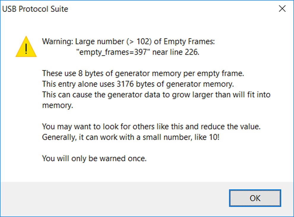
The empty_frames large value may have occurred due to the original trace file having such behavior, which is due to the actual Host taking a long time to process data it receives from the device. The Voyager Trainer has no such processing time, and can therefore use a much smaller value (like 10!) in these locations. Usage: empty_frames=23; insert 23 empty frames here. |
|
host_exp_pid |
PID |
Device Emulation Only Defines the PID that is expected to be received from the Host. The Device Emulator waits until this PID has completed before sending the next generated packet. The key should be assigned to a valid packet identifier string per the USB specification: SETUP, IN, OUT, DATA0, DATA1, ACK, DATA2, or MDATA. PRE and PING are for Hubs only and are not supported. Each memory segment waits forever until it receives the expected PID to its address/endpoint, so the user may have to hand edit the file to achieve the desired results. Each endpoint memory segment acts independently. |
|
Bus Condition Keys |
||
|
reset |
positive integer or LS_EOP |
Host Generation Only Indicates the number of microseconds that single-ended zeros (SE0) are driven onto the bus. Assign a positive integer to this key. This key can also be assigned the string LS_EOP to drive two low-speed bit times of SE0 followed by one bit time of J. |
|
se0 |
positive integer <2500 |
Host Generation Only Same SE0 signal as reset, but the range is in nanoseconds (accuracy: +/- 33 ns). |
|
suspend |
positive integer |
Host Generation Only Indicates the number of microseconds of idle and suspend after the previous packet (for example, for ten milliseconds of suspend, the key should equal 13000). Assign a positive integer to this key. Note that suspend begins after 3 milliseconds of idle. |
|
resume |
positive integer |
Host Generation Only Indicates the number of microseconds of K driven onto the bus. Assign a positive integer to this key. For a proper resume sequence, this should be followed by the condition reset=LS_EOP speed=LOW. |
|
wait_resume |
HERE |
Host Generation Only Place this immediately before a resume=<> statement to implement a device resume, also known as Remote Wakeup. This causes the host to wait for the device to issue the Resume (K) condition before the Host proceeds with its own Resume signaling. This statement MUST be followed by the resume=<> statement. |
|
chirp |
HERE |
Creates a chirp sequence for a High Speed generation. This MUST be used to switch from the default Full Speed behavior to Hi Speed signalling! This should be placed prior to any packet traffic like Start of Frames, etc. Usage: chirp=HERE |
|
wait_vbus |
VALID |
Device Emulation Only Wait for VBUS to go Hi. |
|
termination |
HERE |
Device Emulation Only Set terminations now. |
|
wait_termination |
HERE |
Host Generation Only Only for Voyager. Waits until Device Speed terminations are seen before proceeding. |
|
Keys for Packet Fields |
||
|
speed |
LOW |
Used to cause a low speed packet on a full speed branch. The only legal value is speed=LOW. |
|
addr |
7 bits (0-127) |
Assign a value for the address field. |
|
endp |
4 bits (0-15) |
Assign a value for the endpoint number field. |
|
hub_addr |
7 bits (0-127) |
Host Generation Only Assign a value for the hub_address field of a SPLIT packet. |
|
port |
7 bits (0-127) |
Host Generation Only Assign a value for port field of a SPLIT packet. |
|
data |
(AB CD) |
Assign data bytes for the data field. Use the following syntax: data=(12 34 56 78 90 AB CD EF DC 13 40 78 11 CA 70 65) You can wrap bytes of the data field to the next line. The bytes are in the order they come across the bus, and the bits within the bytes are in MSB to LSB order. The maximum number of guaranteed bytes is 183. However, in some instances, you may be able to transmit up to 1049. |
|
crc |
5 bits (0x0-0x1F) or 16 bits (0x0- 0xFFFF) |
Assign a value for the CRC field. The default value is the correct CRC calculated for the packet. |
|
s |
0 or 1 |
Host Generation Only Assign a value for the S (High Speed SPLIT Start/Speed) field. |
|
sc |
0 or 1 |
Host Generation Only Assign a value for the SC (High Speed SPLIT Start/Complete) field. |
|
e |
0 or 1 |
Host Generation Only Assign a value for the E (High Speed SPLIT End) field. |
|
et |
0 to 3 |
Host Generation Only Assign a value for the ET (High Speed SPLIT Endpoint Type) field: 0 = Control 1 = Isoch 2 = bulk 3 = Interrupt |
|
hird |
4 bits (0-15) |
Host Generation Only Assign the Host Initiated Resume Duration. Default value is 0. For a description of the values 1 through 15, see the Link Power Management Specification. |
|
link_state |
4 bits (0-15) |
Host Generation Only Assign the link state. Currently, the only legal link_state value is 1, for L1 (Sleep). Default value is 0, so set the link_state value to 1. |
|
remote_wake |
0 or 1 |
Host Generation Only Disable or enable Remote Wakeup. Default value is 0, which disables Remote Wakeup. To enable Remote Wakeup, set the value to 1. |
|
eop |
positive integer |
Assign a positive integer for the length of the end of packet (EOP). The default value is the correct length (2 bits of SE0, 1 bit of J). The value is reflected by <val-1> bits of SE0 plus one bit of J. |
|
hi_eop |
(AB CD) Hex |
Used to generate a high speed EOP pattern. The bytes are in the order they come across the bus, and the bits within the bytes are in LSB to MSB order. Maximum number of bytes allowed is 13. |
|
idle |
positive integer or TO_EOP |
Defines the length of idle after the current packet. Assign a positive integer or string to this key. The positive integer indicates the number of full-speed or low-speed bit times. The default value is around 4 bits for Classic speeds and around 150 bits for High speeds. When this keyword is assigned a string TO_EOF, USB Chief automatically calculates the amount of idle remaining in the frame. When handshaking with a device, you can use this key- word to add idle where you anticipate a packet being returned from the device. The idle= key is always associated with the proceeding packet or bus condition, so you should not put file control keys between the packet or bus condition statement and the idle= statement. |
|
marker |
string |
Assign a string in quotation marks to be put in the marker for the defined packet. |
|
raw_data |
(aa bb) |
Voyager M3i Hi Speed Mode only. Use to send a non-modulo 8 number of bits in a classic speed raw_data packet. It is only valid in conjunction with the raw_data statement. Normally, every bit of the array defined in a raw_data=(xx yy) type of statement would be sent. However, particularly in the case where bit_stuff=off, you need more control over the number of bits to be output on the bus. By adding the statement raw_data_bits = 11, only the first 11 bits of the defined bytes are sent. For the following case, raw_data=(8F F0) raw_data_bits=13 the output bitstream would be: 1111 0001 0000 1 (Each byte is described in MSB to LSB format, but is output on the wire in LSB to MSB format.) |
|
raw_data_bits |
integer |
Voyager M3i Hi Speed Mode only. Use to send a non-modulo 8 number of bits in a classic speed raw_data packet. It is only valid in conjunction with the raw_data statement. Normally, every bit of the array defined in a raw_data=(xx yy) type of statement would be sent. However, particularly in the case where bit_stuff=off, you need more control over the number of bits to be output on the bus. By adding the statement raw_data_bits = 11, only the first 11 bits of the defined bytes are sent. For the following case, raw_data=(8F F0) raw_data_bits=13 the output bitstream would be: 1111 0001 0000 1 (Each byte is described in MSB to LSB format, but is output on the wire in LSB to MSB format.) |
|
bit_stuff |
OFF ON |
Voyager M3i Hi Speed Mode only. Assign the string OFF to disable bit stuffing within the current packet. The default value is ON. |
|
sync |
integer 2-40 |
Assign an integer from 2 to 40 to represent the sync field. The integer is the number of zeros transmitted before the one. For Low and Full Speed files, the default value is 7 to give a sync of 00000001. For High Speed files, the default value is 31 resulting in a sync of 00000000000000000000000000000001. |
|
retry ping_on_retry ping_on_nak retry_next_frame |
TRUE FALSE |
Host Generation Only These four keys may be applied to individual packets to override the behavior in a given instance. Normally, they are used in the config_endpoint statement. See their descriptions in the Endpoint Configuration section earlier. |
|
Keys for Class Decoding These keys populate into the .utg. script file automatically when File > Export to .utg runs. These keys do not need to be edited. |
||
|
sd_prod |
|
|
|
sd_vend |
|
|
|
sd_bm_req_type |
|
|
|
sd_interface |
|
|
|
sd_host_id |
|
|
|
sd_class_code |
|
|
|
sd_subclass |
|
|
|
sd_protocol |
|
|
|
sd_end_sd |
|
|