
Device Status Details Window
The status of various device characteristics, such as Terminations, Speeds, Link States etc. can be found in the Device Status Details Window. Open this status window by clicking the button in the lower left section of the Status Bar at the bottom of the Main Menu.
NOTE: This window is not available when using Mercury T2.
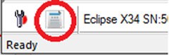
This opens the Device Status Details Window, shown below.
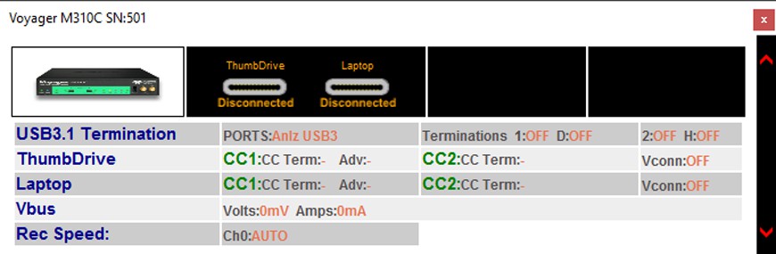
Contents of Device Status Details Window
The contents of this window can vary with the analyzer type being used, as well as the types of traffic being captured (2.0, 3.2, PD) The possibilities include:
-
Name of Device
-
User-assigned name from Recording Options
-
-
Type-C Cable Connection Inversion Status
-
Off: No cable attached
-
Solid Red: Plug is Upside Down, please invert and reinsert
-
Solid Green: Plug is correctly oriented
-
-
3.2 Link Status
-
Off: No traffic or LFPS
-
Solid Yellow: Only Polling LFPS
-
Slow Flashing Yellow: Low Power States
-
Fast Flashing Yellow: Symbol Traffic, Training (TS1/TS2/TSEQ)
-
Solid Green: Link Traffic (U0) LUP, LDN
-
Blinking Green: TPs and DPs (actual traffic)
-
-
USB 3.2 Terminations
-
This includes the ON/OFF terminations of the Unit under Test (UUT), as well as the terminations presented by the analyzer to those UUTs. The Num- bers indicate the analyzer terminations, the others are the DUT and HUT.
-
NOTE: Terminations do not apply for the M310P/M310e analyzer connectors, since those use a Passive Electrical Tap.
-
Type-C Cable Status
-
CC termination
-
Advertised Current Capability
-
VCONN On/Off state
-
-
VBUS Voltage and Current
-
Selected recording Speed
SuperSpeed Termination Status
The lower right middle of the Status Bar shows the SuperSpeed Termination status. (Not applicable to M310P/M310e analyzer connectors, which use a Passive Electrical Tap.)
NOTE: The status is the status of the analyzer port, not of the device or host under test.
When in analyzer-only mode, it shows the termination status of the Analyzer A/1 and B/2 ports AND the status of the far-end Host and Device terminations (Denoted H and D).


Polling occurs when the Application CPU is not busy. The polling interval is reflected in a small dot (.) at the end of the string in the Status Bar.
NOTE: Terminations reflect what the analyzer is presenting to the device or host. The analyzer changes these terminations while attempting to connect the Host DUT and Device DUT together using the SuperSpeed connection protocol. For more information about the Recording buttons on the toolbar, see Recording.
Link Status
The circles 2 and 3 on the lower right of the Status Bar represent the equivalent colors of the link states for USB 2.0 and USB 3.2.
|
Analyzer |
||
|
3+ |
|
USB 3.2 SS+ |
|
|
Off |
No traffic or LFPS |
|
|
Solid Yellow |
Only Polling LFPS |
|
|
Slow Flashing Yellow |
Low Power States |
|
|
Fast Flashing Yellow |
Symbol Traffic, Training (TS1/TS2/TSEQ) |
|
|
Solid Green |
Link Traffic (U0) LUP, LDN |
|
|
Blinking Green |
TPs and DPs (actual traffic) |
|
3 |
|
USB 3.2 SS |
|
|
Off |
No traffic or LFPS |
|
|
Solid Yellow: |
Only Polling LFPS |
|
|
Slow Flashing Yellow: |
Low Power States |
|
|
Fast Flashing Yellow: |
Symbol Traffic, Training (TS1/TS2/TSEQ) |
|
|
Solid Green: |
Link Traffic (U0) LUP, LDN |
|
|
Blinking Green: |
TPs and DPs (actual traffic) |
|
2 |
Solid Yellow: |
FS SOFs, LS EOPs, or control endpoint traffic |
|
|
Slow Flashing Yellow: |
LS Traffic on endpoints other than 0 (resets activity timer as in 3.2) |
|
|
Fast Flashing Yellow: |
FS Traffic on endpoints other than 0 (resets activity timer as in 3.2) |
|
|
Solid Green: |
HS SOFs or control endpoint traffic |
|
|
Flashing Green: |
HS traffic on endpoints other than 0 (resets activity timer as in 3.2) |
|
Exerciser |
|
|---|---|
|
3+ |
USB 3.2 SS+ |
|
Off |
No traffic or LFPS |
|
Solid Yellow |
Only Polling LFPS |
|
Slow Flashing Yellow |
Low Power States |
|
Fast Flashing Yellow |
Symbol Traffic, Training (TS1/TS2/TSEQ) |
|
Solid Green |
Link Traffic (U0) LUP, LDN |
|
Blinking Green |
TPs and DPs (actual traffic) |
|
|
|
|
3 |
USB 3.2 SS |
|
Off: |
No traffic or LFPS |
|
Solid Yellow |
Only Polling LFPS |
|
Slow Flashing Yellow |
Low Power States |
|
Fast Flashing Yellow |
Symbol Traffic, Training (TS1/TS2/TSEQ) |
|
Solid Green |
Link Traffic (U0) LUP, LDN |
|
Blinking Green |
TPs and DPs (actual traffic) |
|
|
|
|
2 |
USB 2.0 |
NOTE: USB Type-CTM Connector Ports Insertion Status:
-
Off: No connector inserted
-
Red: Connector inserted upside-down. Unplug, flip, and re-insert.
NOTE: USB 2.0 Link LEDs operate only while USB 2.0 Recording or Real- Time Statistics (RTS) is running. USB 3.2 LEDs always operate, unless USB 3.2 has been disabled in the Recording Options General Tab.