
Overview
The USB 3.2 tab presents options for setting Recording Ports, Descrambling, Polarity Inversion, Spread Spectrum Clock, Recording/Generating, Simple Filters and Truncate Data Fields, Simple Triggers, Clock/Speed Selection, Analyzer Ports Termination, and Exerciser port settings.
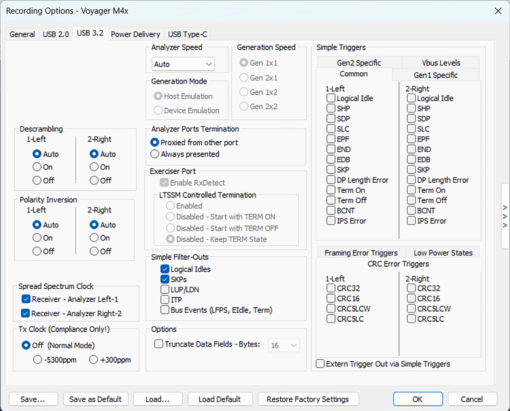
The above image shows the USB 3.2 tab with Common Simple Triggers for USB 3.2 recording. See
Simple Triggers for more on triggers.
Descrambling
In Analyzer Mode, Select Auto to have the analyzer determine the Scrambling state of the incoming data stream on the connector examining the TS1 Packets. You can force the analyzer to either Descramble or not regardless of what is seen in the TS1 packets by selecting On or Off, respectively.
In Exerciser mode, you can chose the Exerciser Transmit Scrambling mode by selecting On or Off. On sends Scrambled data, so the DUT would need to Descramble it. Off sends data without being Scrambled. Auto defaults to sending Scrambled data, just like On. For the DUT side, it works like the analyzer settings, above.
Polarity Inversion
In Analyzer Mode, select Auto to have the analyzer determine the Polarity state of the incoming data stream on the connector examining the TSEQ Packets. You can force the analyzer to either Invert Polarity or not regardless of what is seen in the TSEQ packets by selecting On or Off, respectively.
In Exerciser mode, you can chose the Exerciser Polarity Inversion mode by selecting On or Off. On sends the data Inverted, and Off does not. It is up to the device to handle these cases.
Auto defaults to sending uninverted data just like Off. For the DUT side, it works like the Analyzer settings, above.
NOTE: For Spread Spectrum Clock, select Transmit (Exerciser) to apply Spread Spectrum Clocking to the transmitter. To adjust the receivers to be more tolerant to Spread Spectrum Clocking, select Receive. The Transmitter and Receive commands are independent of each other.
For Recording/Generating, select Analyzer Only, Host Emulation, or Device Emulation.
For Simple Filters, you can Filter-Out Logical Idles, Filter-Out SKPs, Filter-Out LUP/LDN, Filter- Out ITP or Filter-Out Bus Events (LFPS, EIdle, Term).
Simple Triggers: For Downstream and Upstream triggers, you can select Logical Idle, SHP, SDP, SLC, EPF, END, EDB, COM, SKP, K-Code, Symbol Error, RD Error, DP Length Error, Term On, Term Off and BCNT.
Spread Spectrum Clock (SSC)
When operating in Analyzer Mode, it may necessary to manually adjust the SSC settings to be more tolerant to Spread Spectrum Clocking from the device under test. This recording option adjusts the “Receiver” logic on the analyzer ports to improve lock performance.
For M4120, M480x, and M4x, the options are:
-
Receiver - Analyzer Left-1
-
Receiver - Analyzer Left-2
For M310P, M310e, M310C, and M2x, the option is: Receiver
When selected, the analyzer Reference Clock will apply “down-spread” to its own internal Receiver Reference Clock to better track SSC signaling. When clear, the Analyzer Receiver Reference Clock will be set to the nominal data rate.
Analyzer Ports Termination
This setting identifies the Superspeed Rx termination approach on the analyzer ports. There are two main options:
-
Proxied from other port
-
Always presented
Proxied from other port mode (the default) is designed to recognize USB 3 hosts and devices attached to one port of the analyzer, then present terminations to DUT attached to the other port. However, some cases have timing that can cause the Host and Device not to connect or fall back to USB 2.0; in this case Always presented mode. In Always presented mode, there is a fixed Rx termination presented from the analyzer port regardless of other port connection status.
NOTE: Analyzer Ports Termination settings do not apply to the M310P/M310e analyzer connectors, since they use a Passive Electrical Tap. Termination is therefore passed through directly.
Exerciser Port Settings
There are two settings for exerciser ports:
-
Enable RxDetect: Designed to recognize USB 3 hosts and devices and present a SS termination to them when they are plugged in.
-
LTSSM Controlled Termination: If Enabled, the Exerciser will automatically present SuperSpeed receiver termination is accordance with the Type-C specification and the USB 3 Link Training Status State Machine.
Disabling the feature will allow complete control of the termination state through an Exerciser script (.usb3g) file, which may be desirable for testing compliance scenarios. The Disabled setting further allows the user to select whether termination will be enabled (Start with TERM ON), disabled (Start with TERM OFF), or unmodified (Keep TERM state) when the recording options are initially applied.
Truncate Data Fields
Truncate the data fields in a Data Payload packet to the length specified in the pull-down selection. The actual amount captured is at LEAST the amount selected and may be up to 8 bytes more, depending on traffic, to increase efficiency of the analyzer hardware.
NOTE: Truncating the payload allows more packets to fit in a trace, but it has the potential to prevent accurate decoding to higher layers (transfers, SCSI, etc).
Simple Triggers
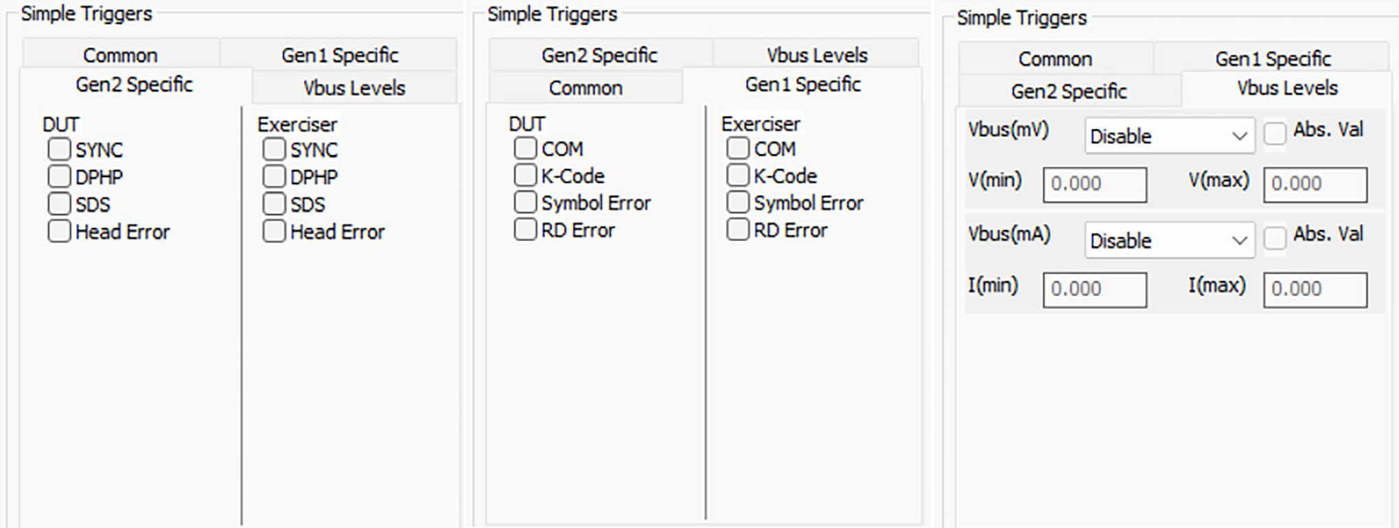
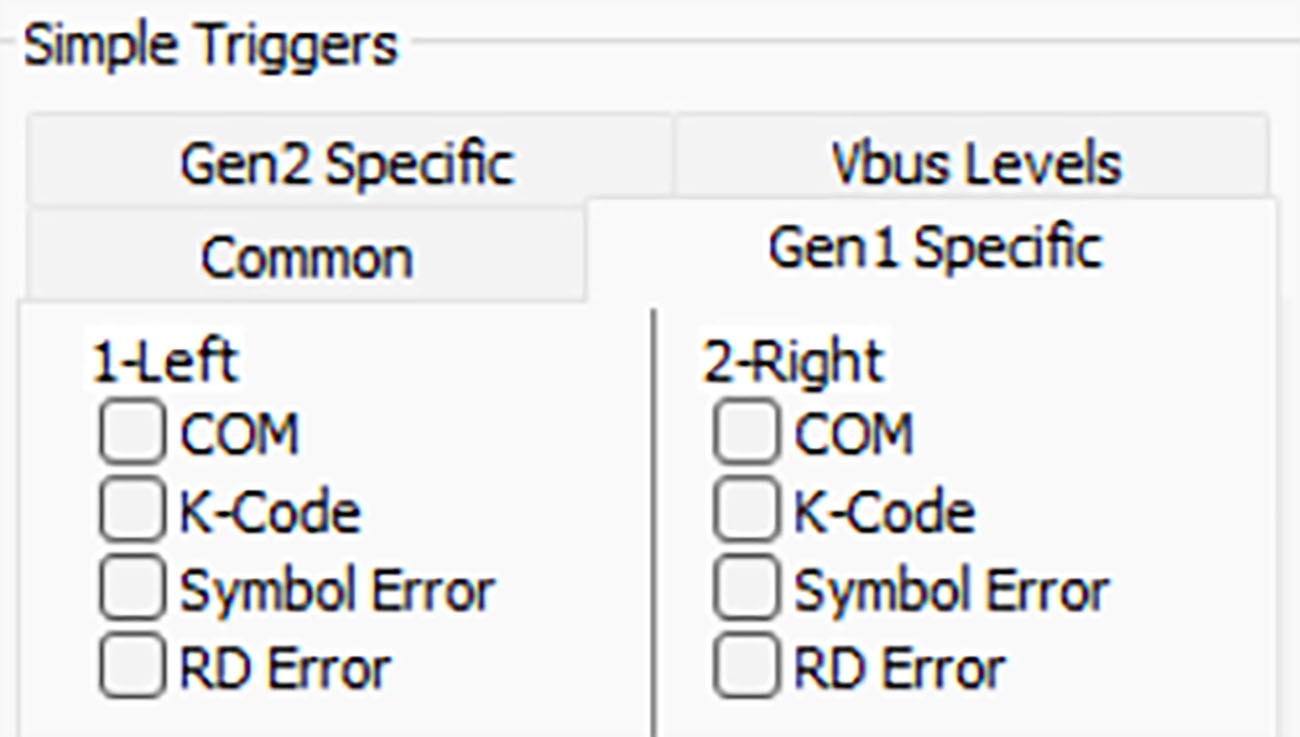
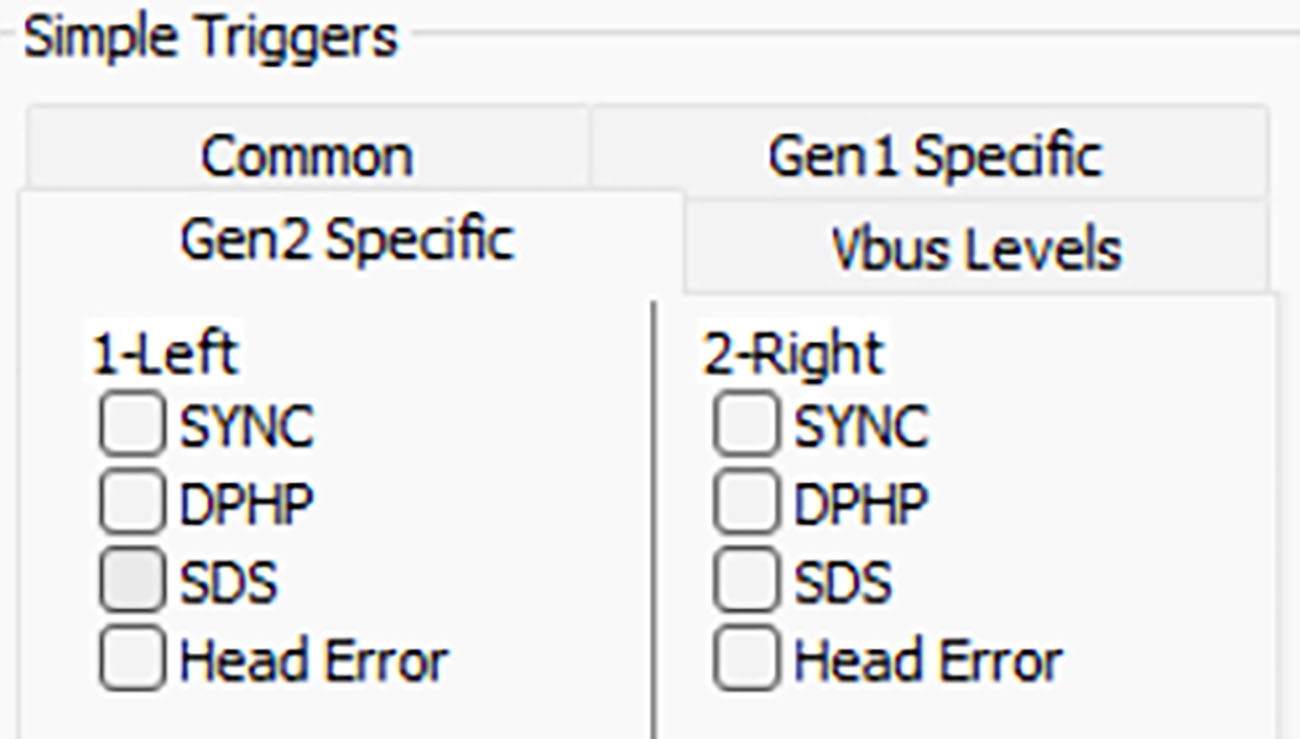
In addition to the Common triggers, there are also:
-
Gen 1 Specific
-
Gen 2 Specific
-
VBUS Levels
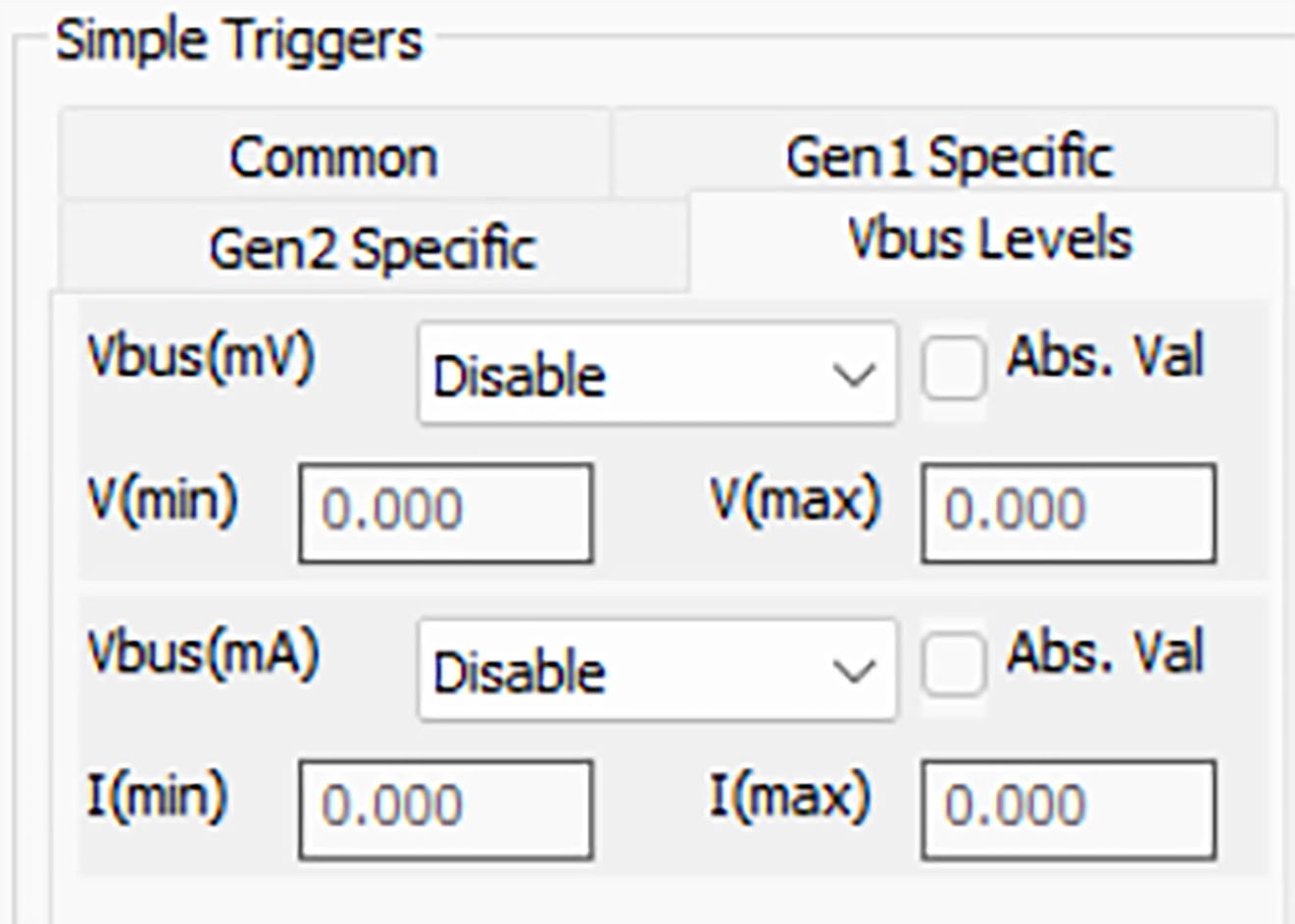
You can specify V(min) and V(max) or I(min) and I(max) with the following conditions:
-
Disable
-
Less Than
-
Greater Than
-
Between
Absolute Value (VBUS Levels)
If you don’t know which direction the power is coming from (whether it’s being sourced or sinked) you can select the Abs. Value and then set the voltage and current (min) and (max) and the select conditions will trigger the analyzer. See below.
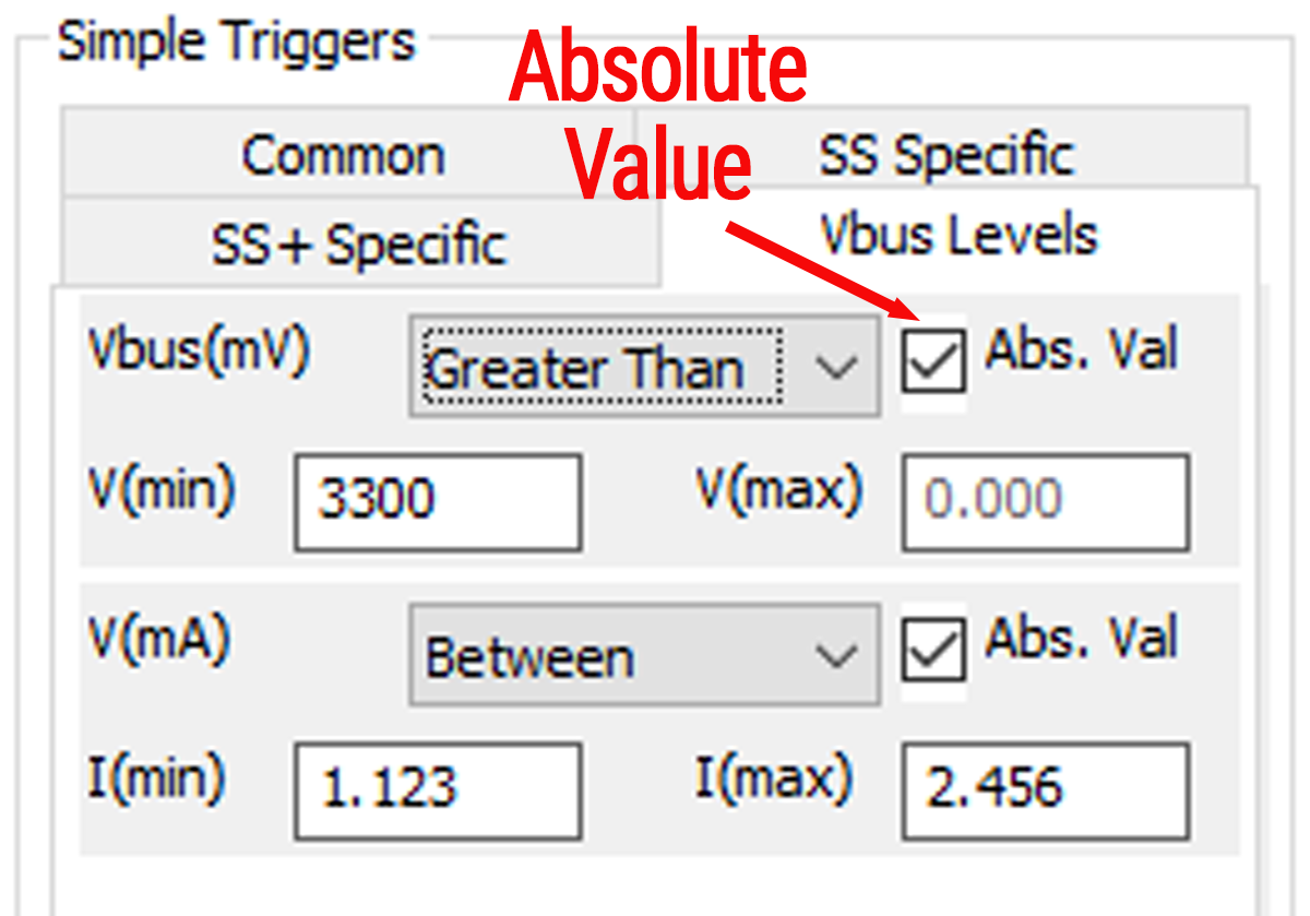
In the case shown above the analyzer will trigger if the magnitude (positive or negative) of the VBUS is greater than 3300 mV and the magnitude of the current (positive or negative) is between 1.123 mA and 2.456 mA.
Other Simple Triggers
-
CRC Error Triggers: For Downstream and Upstream triggers, use CRC32, CRC16, CRC5LCW, and/or CRC5LC.
-
Framing Error Triggers: For Downstream and Upstream triggers, use SLC, SDP, SHP, END, SS + DPHP.
-
Low Power States: For Downstream and Upstream triggers, use U1, U2, and/or U3. For U2, trigger only works for explicitly directed entry to U2. It does NOT work for the case when U1 times out and implicitly goes to U2, as the bus engine does not track this timeout value.
If you trigger on a CRC error type, the traffic in the trace file at or near the trigger may display as IPS (Inter-packet symbols), because the software might not detect proper framing symbols. Consequently, searches for CRC errors may not find the CRC trigger location.
To cause a trigger signal to appear on the External Trigger Out facility when the simple trigger(s) occur, select the External Trigger Out with Simple Triggers checkbox.