
Overview
The USB 2.0 page presents options for setting:
-
Analyzer Trace Speed: Select Auto-Detect, Low, Full, or High.
-
USB On-the-Go: Check On-the-Go SRP. Optionally select Dual Role Devices as 2 DRDs and enter device names. Optionally, assume that B is the first host.
-
Generator-related Parameters: Choose parameters and device address location.
-
Options: Truncate data fields
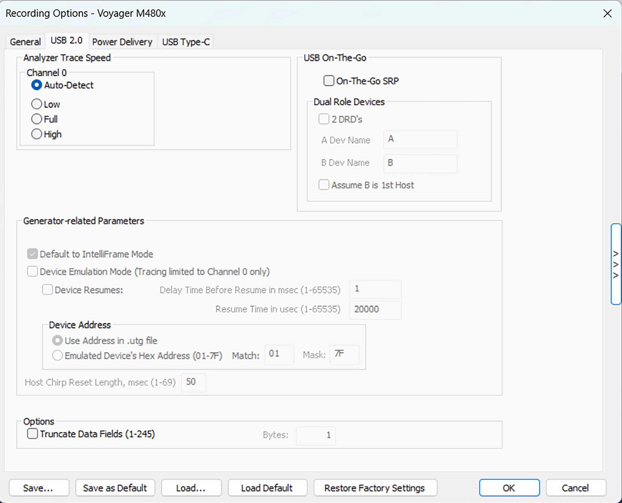
Analyzer Trace Speed
This option sets the speed of the traffic recorded by the analyzer. The default setting is Auto-Detect. This setting tells the analyzer to discover what speed traffic is running and to label packets accordingly. Auto-Detect will find a speed and lock on it permanently for the duration of the trace. If traffic speed changes, it will not be seen by the analyzer. If you are having problems with your recordings, you might try setting the traffic speed to one of the fixed values—Low, Full, or Hi Speed. These settings are used when you want to manually set the traffic speed. It can take ~ 6 ms for the High Speed detection to occur in Auto-Detect mode, so it is possible to miss some packets with this method.
One side effect of using Auto-Detect Speed selection is that the first set of High Speed Chirps that occur prior to the first packet is not recorded. The Auto-Detection mechanism is looking for a match on a packet pattern, so it does not see the Chirp signaling (which is only visible to the High Speed Detection circuitry).
NOTE: If you already know the speed of the device you are working with, it is better to set the speed explicitly.
In some rare cases, auto-detection circuitry causes Full Speed devices to fail to enumerate on plug-in. Changing the analyzer speed to Full Speed can sometimes solve this problem.
Setting the speed to one of the fixed values can be useful for debugging purposes. For example, if a device that is producing numerous errors at a particular speed, you may wish to set the recording to that speed in order to ensure that the analyzer does not misread the error packets and label them the wrong speed. While it is unlikely that the analyzer will mislabel packets in this way, manually setting the recording speed guarantees that the analyzer always records packets at the correct speed.
When selecting a fixed speed, the analyzer will stay on that speed regardless of traffic. To capture more than one speed requires looping through multiple 2.0 ports (daisy-chained analyzers such as Voyager or Advisor T3)
Notes on Hi-Speed Recordings
Erroneous chirp blocks can be recorded on an idle bus when the Device has its FS terminations on while the Host has HS terminations connected. This causes a small differential voltage (“tiny-J”) on the USB bus that causes false Chirp detection.
This condition occurs during speed negotiation:
-
On a HS bus, the condition is momentary just before the device chirps.
-
On a CS bus, the condition occurs both before and after the device chirp (until the end of Reset). The user is discouraged from using Speed = HIGH to record signals on a classic speed bus.
-
The analyzer stops recording anything for 2.5 milliseconds following a FS_K state (which is at least 2 microseconds long). This is to avoid presenting “garbage” which is a byproduct of the high-speed probe settling down.
USB On-The-Go
The USB On-The-Go option sets the Analyzer to record the USB On-The-Go traffic. This protocol lets you run two devices, specify one of them as the host, one of them as the device, and to assign each device a name.
Generator-Related Parameters
You can set traffic generation parameters:
-
Disable Generator Memory: Use the whole Capture Buffer for the trace. Only available on some models.
-
Default to IntelliFrame Mode: Rather than Bitstream Mode.
-
Device Emulation Mode: Limit tracing to Channel 0. You can select Device Resumes, then set the Delay Time Before Resume (in milliseconds, from 1 to 65535) and Resume Time (in milliseconds, from 1 to 65535).
You can set traffic generation parameters for the Device Address:
-
Use Address in .utg file: The traffic generation file has an address.
-
Emulated Device’s Hex Address (01-3F): Enter the Mask and Match for the emulated device.
You can also enter the Host Chirp Reset Length (in milliseconds, from 1 to 69).
Data Truncation Option
Truncate Data Fields: Allows data fields to be truncated during recording in order to save analyzer memory and allow recording of more packets. Enter a minimum data length value in the Bytes box. The system truncates the data to the stated value (or up to 5 bytes more to optimize operation efficiency in the analyzer hardware).
NOTE: Truncation of data may cause incorrect transaction or transfer decoding.