
The Link Settings, Spread Spectrum Clock, and Polarity Inversion recording options for the M4120, M480x, and M4x in USB4 Analyzer Mode appear in the USB4 > General pane (below). From the USB4 tab, you can also access various Triggers and Filters.
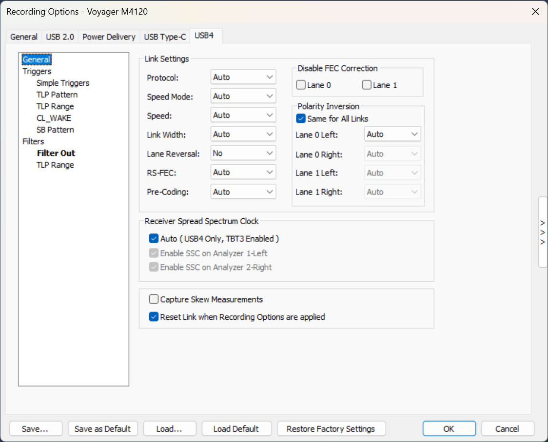
General Pane
Protocol
-
TBT3: Causes the software to interpret the packets and behavior according to the TBT3 specification. For example, if a new field is used in USB4 that was Reserved in TBT3, it will be shown as an error.
-
USB4: Interprets all packets and behavior according to the USB4 specification.
Speed Mode
-
Rounded: USB4 clock rate of 20.000 Gbps (Gen 3) or 10.000 Gbps (Gen 2)
-
Legacy: TBT3 clock rate of 20.625 Gbps (Gen 3) or 10.3125 Gbps (Gen 2)
Speed
-
Auto
-
Gen 2
-
Gen 3
-
Gen 4 (M480x and M4120 only)
Note: Gen 4 capture requires a Gen 4 license. With Auto selected, the link may still train at Gen 4 speed even without the license, but recording stops and a final packet is added to the trace explaining that Gen 4 capture is not enabled.
Before capturing USB4 Gen 4 traffic with a Voyager M4120 or M480x, run USB4 Gen 4 Receiver Tuning for the connected test setup.
Link Width
-
Auto
-
Single-Link x1
-
Symmetric x2
Note: Asymmetric capture requires the USB4 Asymmetric license. With Auto selected, the link may still establish an asymmetric configuration even without the license, but recording stops and a final packet is added to the trace explaining that Asymmetric capture is not enabled.
Lane Reversal
-
No
-
Yes
RS-FEC
-
Auto
-
FEC Encoded
-
Non-FEC Mode
Pre-Coding
-
Auto
-
Enabled
-
Disabled
Disable FEC Correction
Controls whether the Analyzer tries to apply FEC correction to its capture data, or ignores it. Default is to apply the corrections (checkboxes cleared)
-
Lane 0
-
Lane 1
Polarity Inversion
Same for All Links: Used to force a polarity regardless of that indicated in the training.
Note: This is seldom needed, so it is normally set to Auto.
-
Lane 0 Left – Auto Off/On
-
Lane 0 Right – Auto Off/On
-
Lane 1 Left – Auto Off/On
-
Lane 1 Right – Auto Off/On
Receiver Spread Spectrum Clock
This recording option automatically adjusts the “Receiver” logic on the analyzer ports to improve lock performance. Clear the checkboxes to disable.
Capture Skew Measurements
Enables capture of lane-to-lane skew measurements. These measurements are performed periodically on TSNOS packets, which must be present in the trace to obtain readings.
The accuracy is approximately +/- 5 ns.
Reset Link when Recording Options are applied
The analyzer cannot recover USB4 traffic if capture settings change while a link is active. When this option is enabled, the analyzer will momentarily break the link between analyzer ports whenever Recording Options are applied. This ensures the Host and Device establish a new link that can be captured.
Triggers Pane
Simple Triggers Pane
Select Simple Triggers to open this pane. There are trigger options for Gen2/3 and Gen4, and Left or Right ports. Select any number of the items listed to cause a trigger to occur when the event is seen by the analyzer.
Note: Min Hdr Gap Err provides a trigger option that checks the traffic based on the USB4 transport layer Minimum Header Gap constraints and triggers in case of any violation.
TLP Pattern Trigger
These are packets on the High Speed USB4 lanes. The first word denotes the USB4 Header which is one DWORD, followed by 4 DWORDS of untyped traffic.
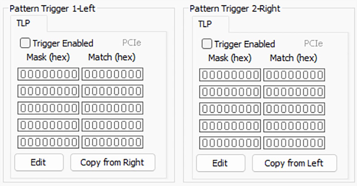
Edit TLP Mask Match Pattern Options
When you select the Edit button in the Pattern Trigger, it launches a dialog box for editing the TLP.
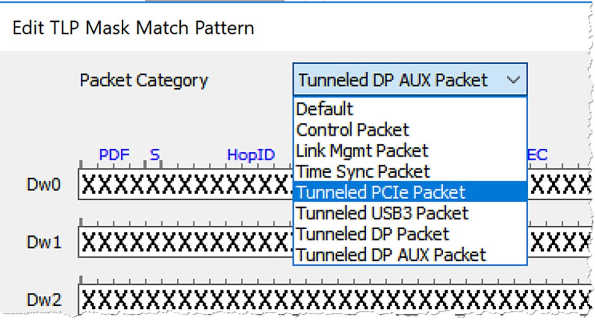
Note: The Dw4 row is marked with an asterisk (*) because it applies to Gen 2 and Gen 3 traffic only. For Gen 4 traffic, only Dw0 through Dw3 are matched.
You can select the Packet Category you want to trigger from the drop-down list. Categories include:
-
Default
-
Control Packet
-
Link Mgmt Packet
-
Time Sync Packet
-
Tunneled PCIe Packet
-
Tunneled USB3 Packet
-
Tunneled DP Packet
-
Tunneled DP AUX Packet
If you chose Tunneled PCIe Packet, the following options are available in DW0:
-
PDF
-
Supplemental ID
-
HopID
-
Length
-
HEC
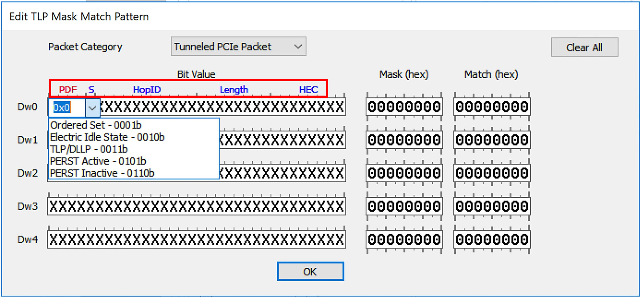
For PDF, you can choose from the following options:
-
Ordered Set
-
Electrical Idle State
-
TLP/DLLP
-
PERST Active
-
PERST Inactive
An example with each option selected is shown in below.
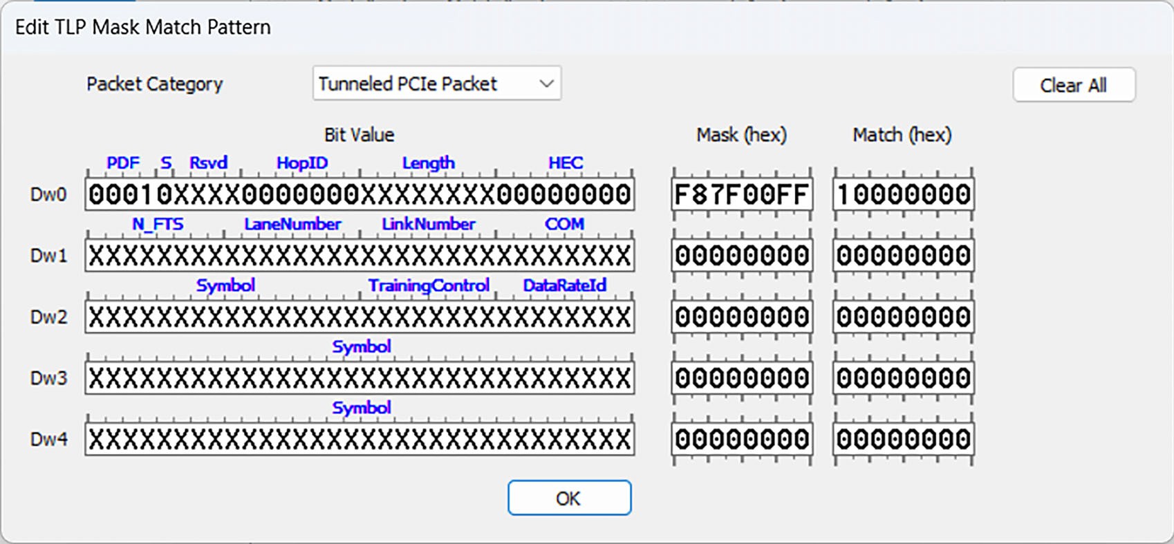
Once you click OK, the Trigger Pattern you selected is shown in the Recording Options dialog boxv (below), and the PCIe text in the Pattern Trigger pane is displayed.
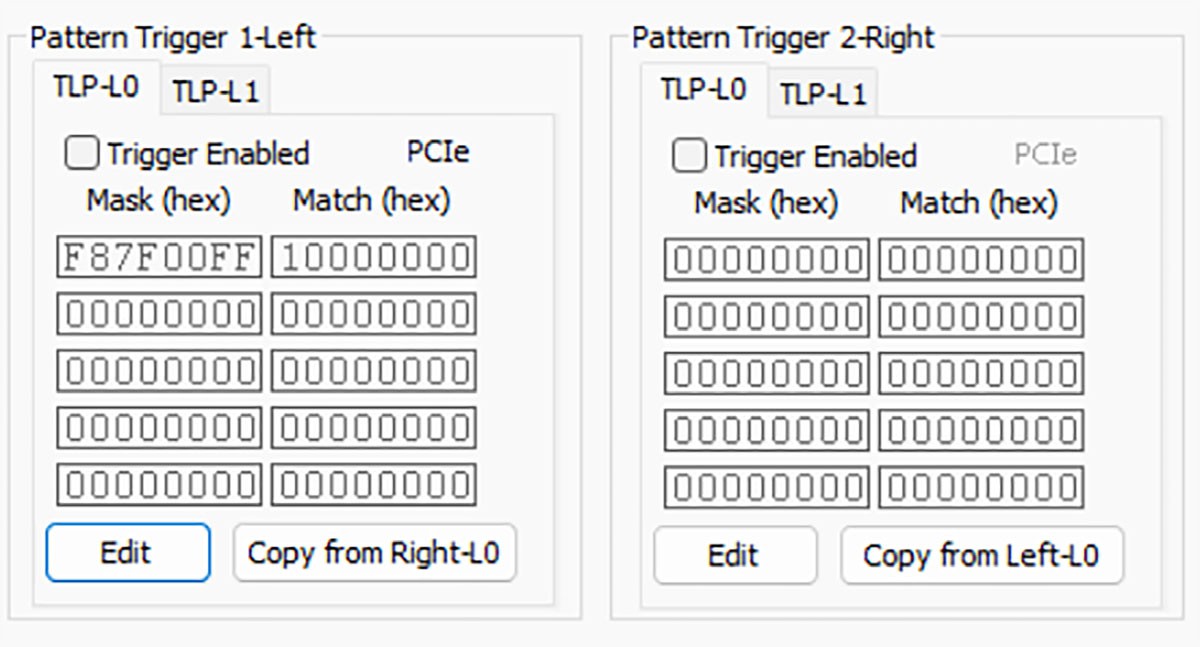
Tunneled PCIe Packet
Check this option if you are trying to trigger on a PCIe TLP. In the special case of PCIe tunneling, the pattern being set for matching is applied simultaneously to the following DWORDS:
-
DWORD0-DWORD1-DWORD2-DWORD3-DWORD4
-
DWORD0-DWORD3-DWORD4-DWORD5-DWORD6
The above compensates for the fact the PCIe can insert a 2-DWORD DLP at the beginning of a tunneled packet, causing the PCIe TLP to start at DWORD 3.
The other Packet Types chosen from the drop down menu function in a similar manner.
TLP Range Trigger
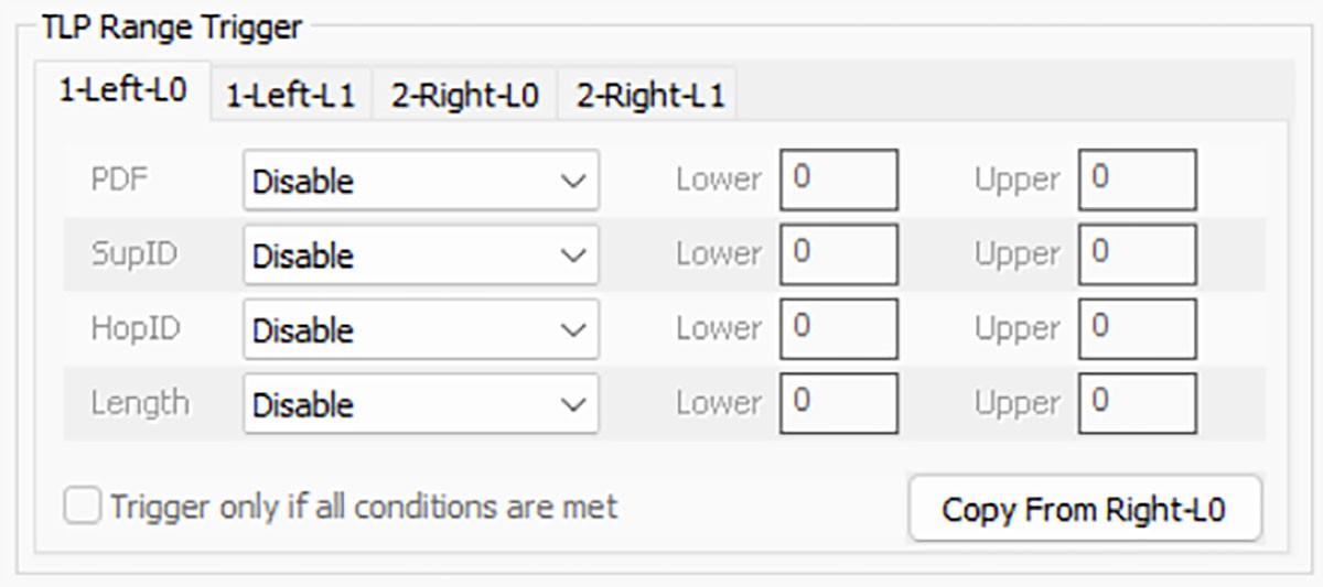
This allows you to trigger on TLPs that match specific ranges of PDF, Supplemental ID, HopID, and Length. You can choose to trigger if one or all of the defined conditions occurs.
CL_WAKE Trigger
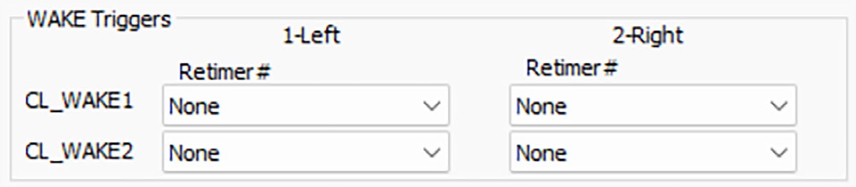
Allows triggering on CL_WAKE packets with specific re-timer indexes.
Sideband Pattern Trigger
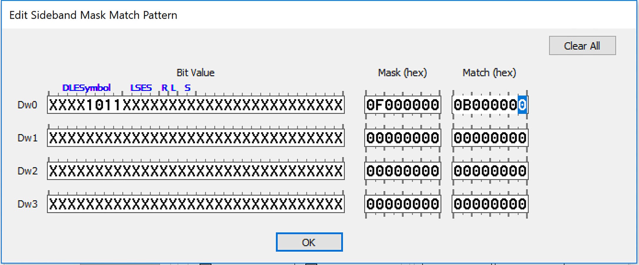
This is used on SideBand traffic to trigger up to 4 DWORDS of pattern matching.
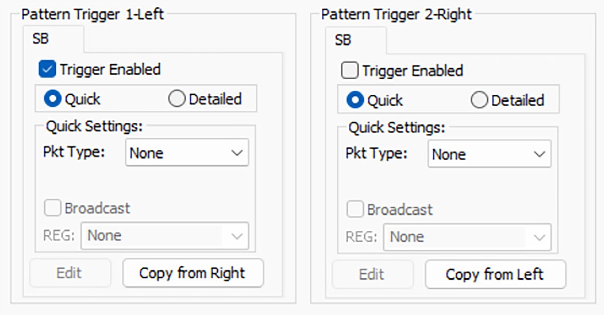
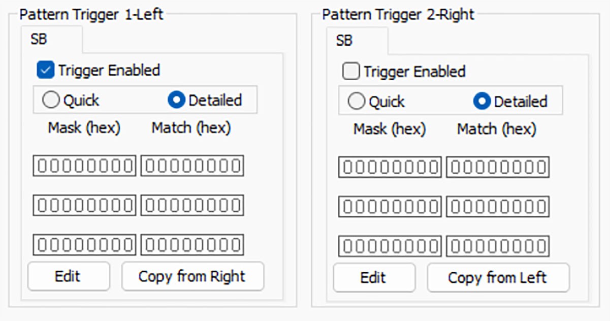
Trigger Enabled: This turns the triggering off or on based on the defined pattern. The pattern can be preserved in either the triggering mode or with it turned off.
Copy from Right/Copy from Left: To simplify setting patterns you want to match from either transmitter, click on this button to copy the pattern from the OTHER side to the current one.
The SB pattern trigger definition provides both Quick and Detailed options. In Quick mode, the software displays a list of SB packet fields with allowed options for each field based on the latest USB4 specification. The image below shows editing SB pattern trigger in Quick mode.
Choose the Detailed mode to define the desired pattern based on sequence of DWORD match/mask. This option allows you to define any customized pattern that not possible through standard field definitions. The image below shows editing SB patterns in Detailed mode.
Click Edit to display a new window so you can edit match/masks to define a desired pattern. The image below shows SB patterns.
Filters Pane
Filter Out Pane
Select the items you do not want captured in the trace file. This reduces the size of the trace file and/or reduces the amount of capture memory used.
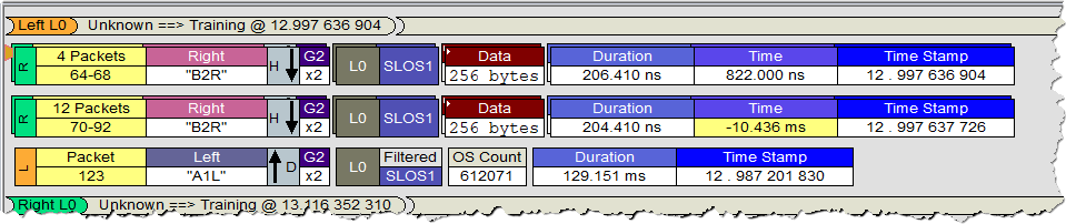
Note: Partial SLOS/WAKE/TS (Rec Buffer Save) is a useful filtering option for users who need to capture some critical OSs that cause LSSM state change, but do not want to fill up the memory with all OSs. This option keeps a few OSs in trace and filters out the rest of packets. CATC Trace view shows the count of filtered OSs with specific packet types in the trace. The image below shows the trace with partial OS filtering enabled.
The default number of ordered sets that are shown before filtering is 100, and this value can be customized via the Pre-Filter Count setting.
Note: USB3.2 LFPS filter is a partial filtering option that keeps “USB4 LFPSs” in trace and only filters USB3.2 LFPSs that happens before entering USB4 mode.
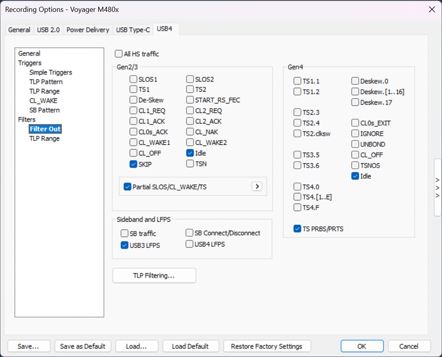
TS PRBS/PRTS allows for filtering out the PRBS11 (in case of TS1) or PRTS7 (in case of TS2, TS3, and TS4) portion of Gen 4 Training Sequences. Only the headers are retained in the capture.
When you select TLP Filtering from the Filter Out tab, these options appear:
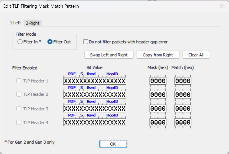
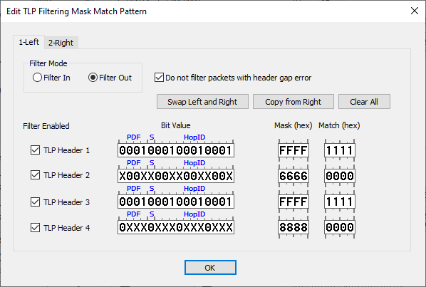
Using this window, you can define Filter IN (capture only TLP traffic with associated HOP ID(s)) criteria or Filter Out (do not capture TLP traffic with associated HOP ID(s)) criteria separately for left/right port. There are options to swap left/right patterns or copy pattern from other side for quicker pattern definition.
Note: Filter In is marked with an asterisk (*) because it applies to Gen 2 and Gen 3 traffic only. Gen 4 traffic supports Filter Out mode only.
You can also use the Copy from Right and Copy from Left buttons to simplify editing the options.
In Filter Out mode, when Do not filter packets with header gap error is checked, it keeps TLP packets in trace with a header GAP violation.
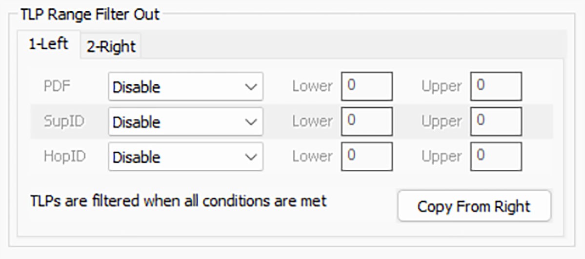
This allows you to filter out TLPs that match specific ranges of PDF, Supplemental ID, and HopID.
Individual Lane Triggering
Select this checkbox to allow triggers to be configured on a per-lane basis.