
The Recording Rules page is a workspace for creating recording rules, which determine how the analyzer records traces. Recording rules are combinations of events and actions. Note that Recording Rules for USB 3.2 currently do not support more than two independent states.
An event and the action or actions associated with it form a rule state. One or more states are encapsulated in a sequence.
NOTE: There can be from one to 512 states within a sequence. You can associate one or more events with each state, and you assign each event a different action or the same action.
A sequence that has only one state is called a single-state sequence. The analyzer continuously watches for each event in the sequence and executes the corresponding action if the event is detected.
A sequence that has multiple states is a multi-state sequence. The states are arranged in a hierarchy, with a top state and successively lower states. Only one state in a multi-state sequence is active at a time. The analyzer does not go to a successive state unless it is directed to do so by the previous state.
Sequences are described in detail in USB4 Recording Options. Briefly, creating a rule involves the following steps:
-
Creating Event buttons in the Available Events area.
-
Drag-and-drop of Event buttons to the appropriate areas (cells) in the Main Display area.
-
Assigning an action or actions to each Event button.
Navigating the Recording Rules Page
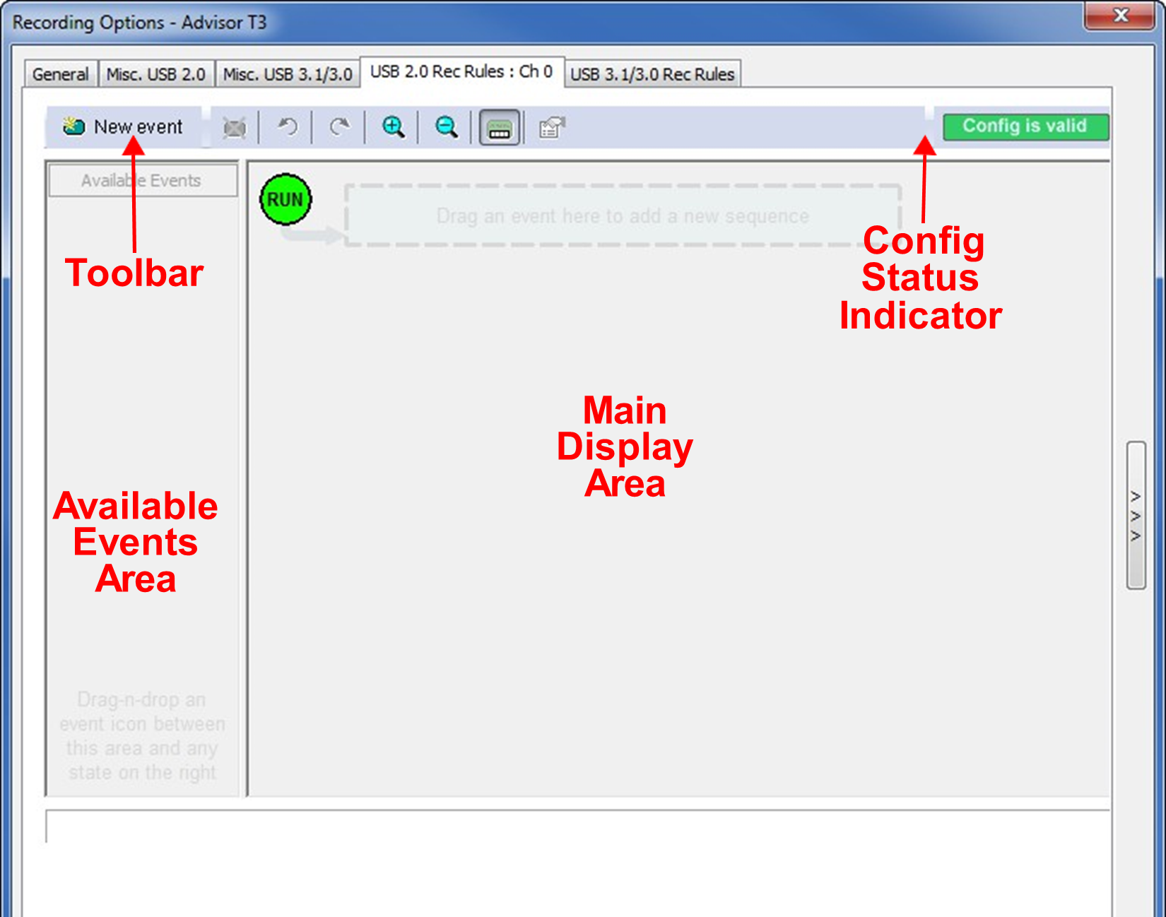
The page has the following areas:
-
Toolbar: Contains buttons that control the Recording Rules page.
-
Available Events Area: Area where you can park Event buttons that you intend to use in the Main Display area.
-
Main Display Area: Area where you configure trigger and filter rules. You configure rules by dragging Event buttons from the Available Events area and then assigning actions to those buttons.
-
Config status Indicator: A button that indicates if the rule is valid or invalid. If a trigger or filter rule is configured correctly, the button is green and indicates Config is Valid. If a rule is not configured correctly, the button is red and indicates Config is Invalid.
-
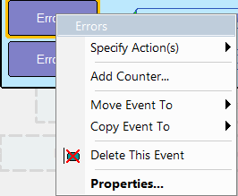
Pop-Up Menus: When you right-click a button or area in the Recording Rules page, a context-sensitive pop-up menu appears that lets you do operations that relate to that button or area.
Properties Dialogs: When you click the Show/Hide Properties Dialog button for an event, action, or state, a dialog allows you to perform the same operations as in the pop-up menus.
Recording Rules Toolbar
The Recording Rules toolbar buttons control the rules for your recordings.

|
Button |
Function |
|
Button |
Function |
|---|---|---|---|---|
|
|
New Event. Creates a new event in the Available Events area. |
|
|
Zoom Out. Makes the display appear smaller. |
|
|
Delete Event. Deletes the selected event. |
|
|
Show/Hide Channels. Shows or hides the channel icon on the Event button. |
|
|
Undo. Undoes the change made to Recording Rules page. The Undo buffer has unlimited size. |
|
|
Show/Hide Properties Dialog. Shows or hides the properties dialog of the selected event, action, or state. |
|
|
Redo. Restores changes done to the Recording Rules page. |
|
|
This appears when the current Recording Rules configuration can be executed by the hardware. |
|
|
Zoom In. Enlarges the display (see note). There are five zoom levels. The default level is the middle one. |
|
|
This appears when the current Recording Rules configuration cannot be executed by the hardware. |


NOTE: If you use a mouse with a wheel, you can zoom by holding down the CTRL key and rolling the mouse wheel.
Creating Event Buttons
To create a rule, first create one or more Event buttons. They appear in the Available Events area. You then can drag-and-drop them into the Main Display area.
To create event buttons:
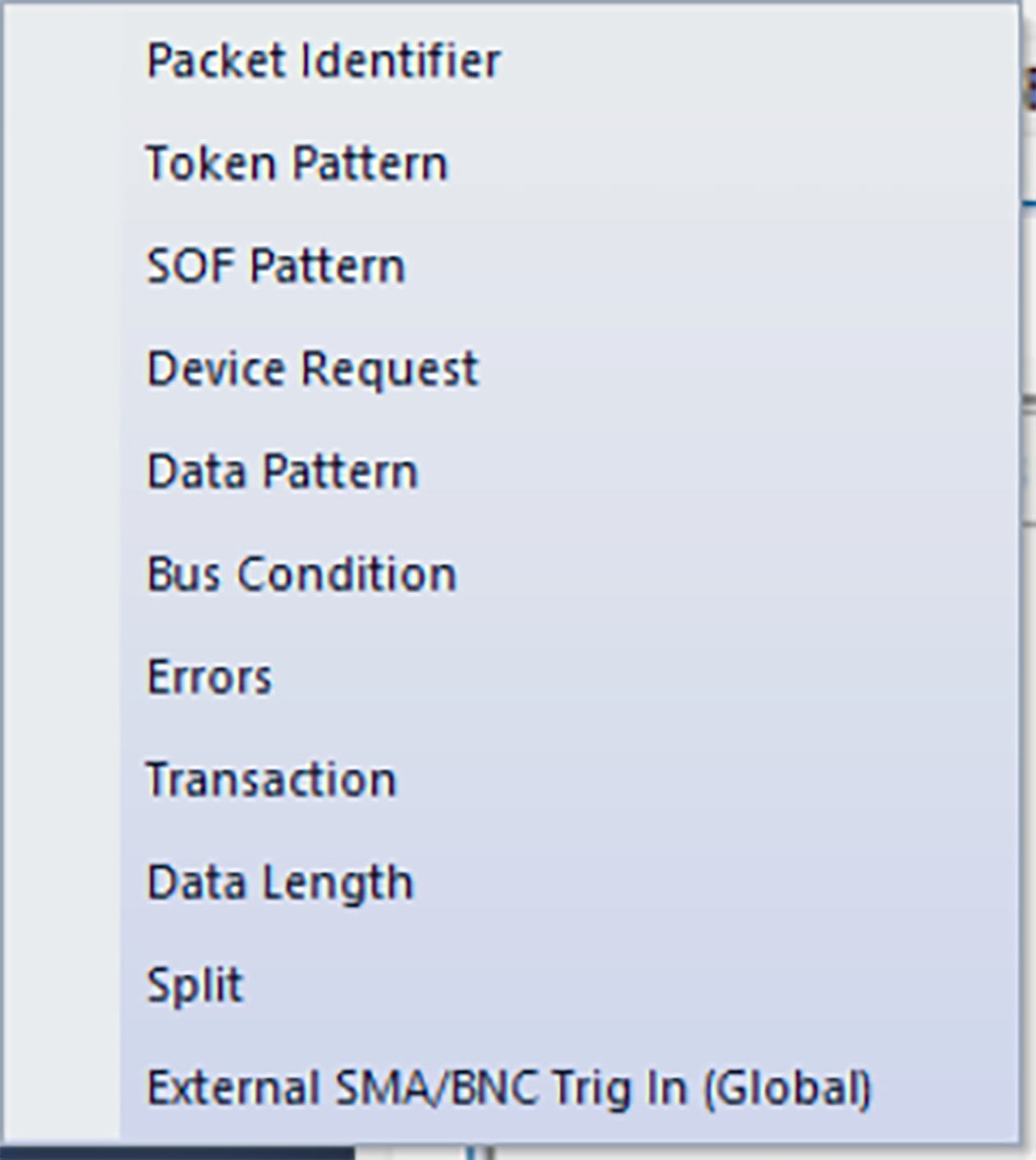
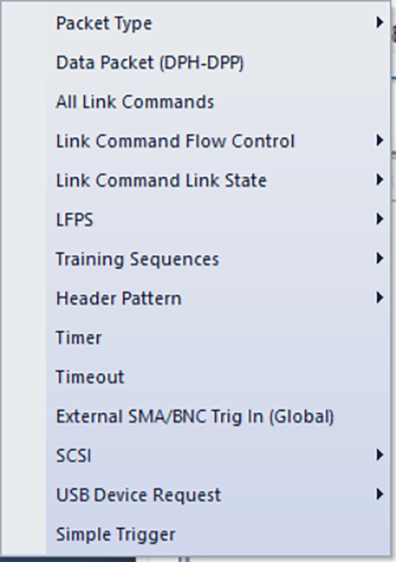
Click the New Event button at the left side of the toolbar to display the New Event pop-up menu (shown below).
|
|
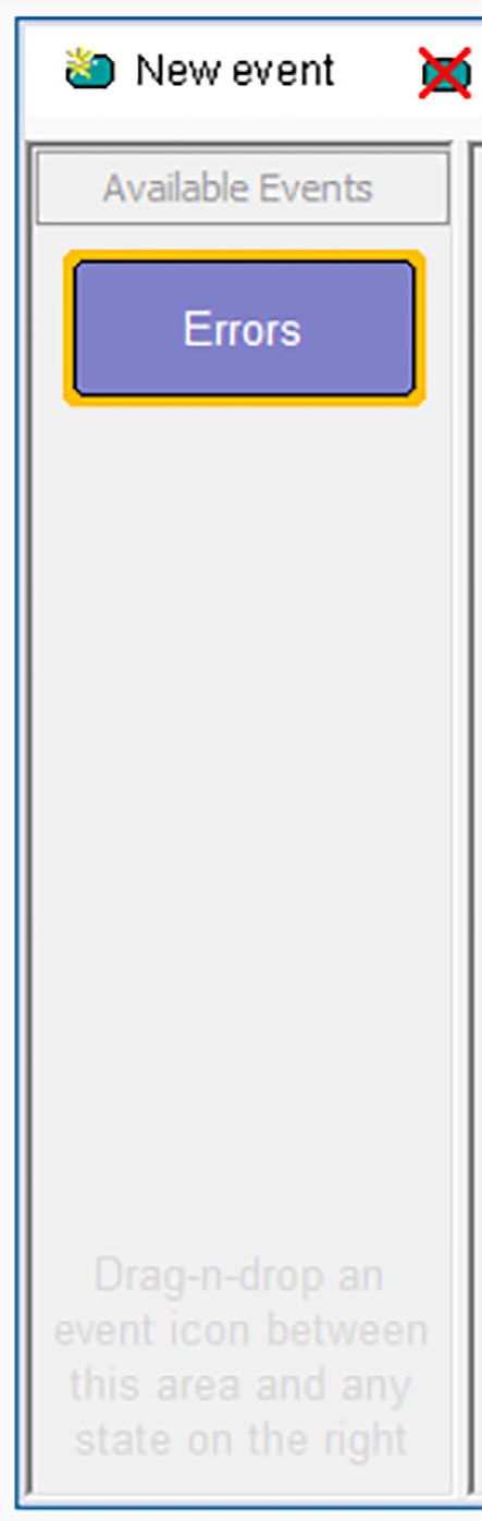
Select an event, such as Errors. The event appears as a button in the Available Events area (below).
Dragging a Button to the Main Display Area
After you create an Event button in the Available Events area, you can drag the button to the Main Display area and drop it in the appropriate cell (a cell is a grayed-out rectangle with a dashed line around it). You can think of each cell as a target for drag-and-drop of an Event button.
There are two types of cell that might appear: Sequence cell and State cell. In the Main Display area, they are labeled as follows:
-
Sequence cell: Drag an event here to add a new sequence.
-
State cell: Drag an event here to add another state.
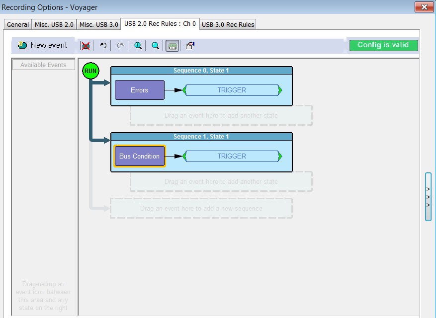
If there currently are no events in the Main Display area, a single sequence cell appears at the top of the area.
To drag-and-drop the Event button:
-
Click and grab the Event button in the Available Events area.
-
Drag the button to the cell. When the button is in the cell, a dashed highlighted outline appears around the cell. Drop the button in the cell.
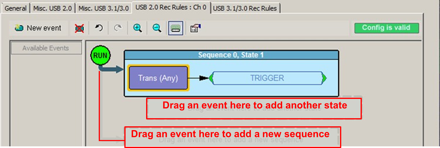
The default label for the first cell is Sequence 0, State 1. As described later in this section, you can change that label using the Properties pop-up for that cell.
Two new cells appear under the first cell. The first of these new cells is a state cell that allows you to create another state in rule Sequence 0 (to make Sequence 0 a multi-state sequence: Sequence 0 State 1 and Sequence 0 State 2). You can have up to 7 states in one sequence.
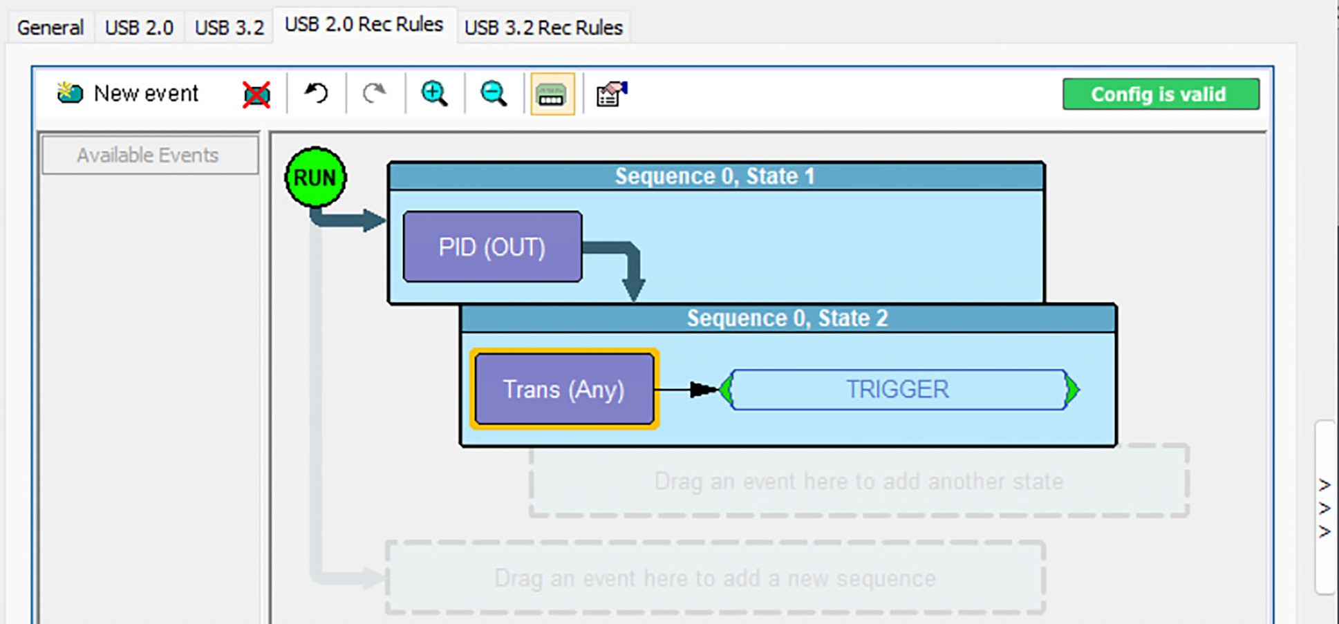
The second of the new cells is for creating a separate sequence.
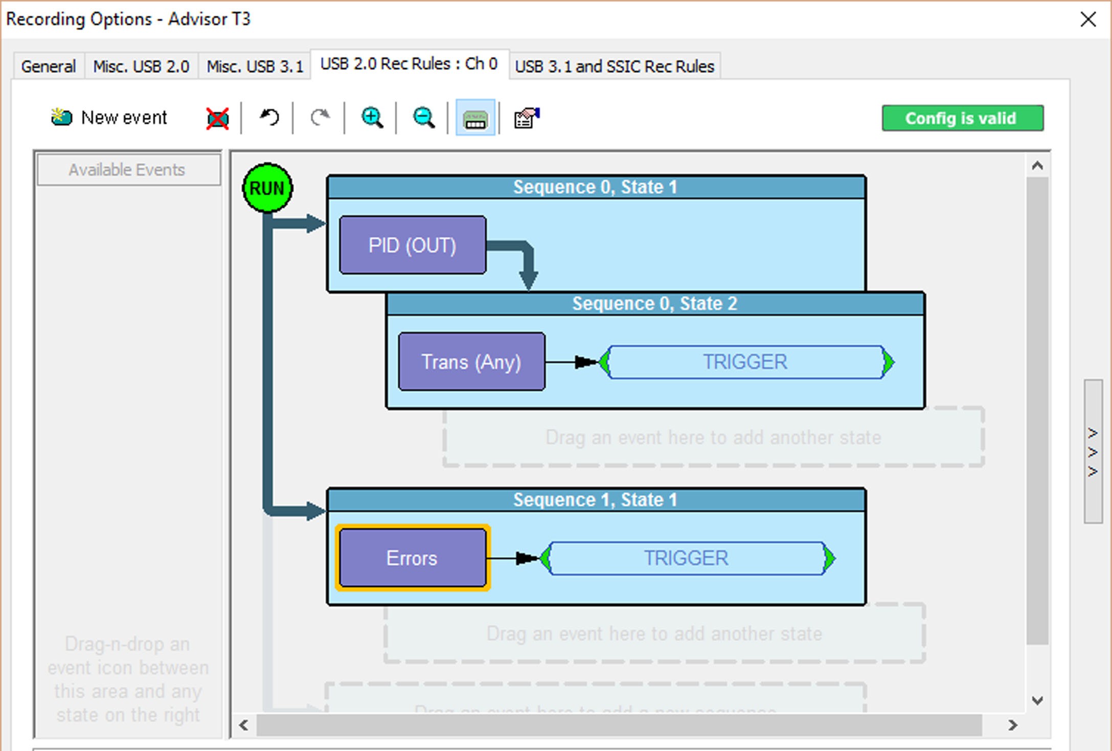
You can define up to 8 sequences.
Assigning an Action
After you have dropped the Event button in a cell in the Main Display area, you can assign an action to the event.
NOTE:If you do not assign an action to an Event button, the analyzer ignores the event.
To assign an action to an Event button:
Right-click the Event button to display a pop-up menu.
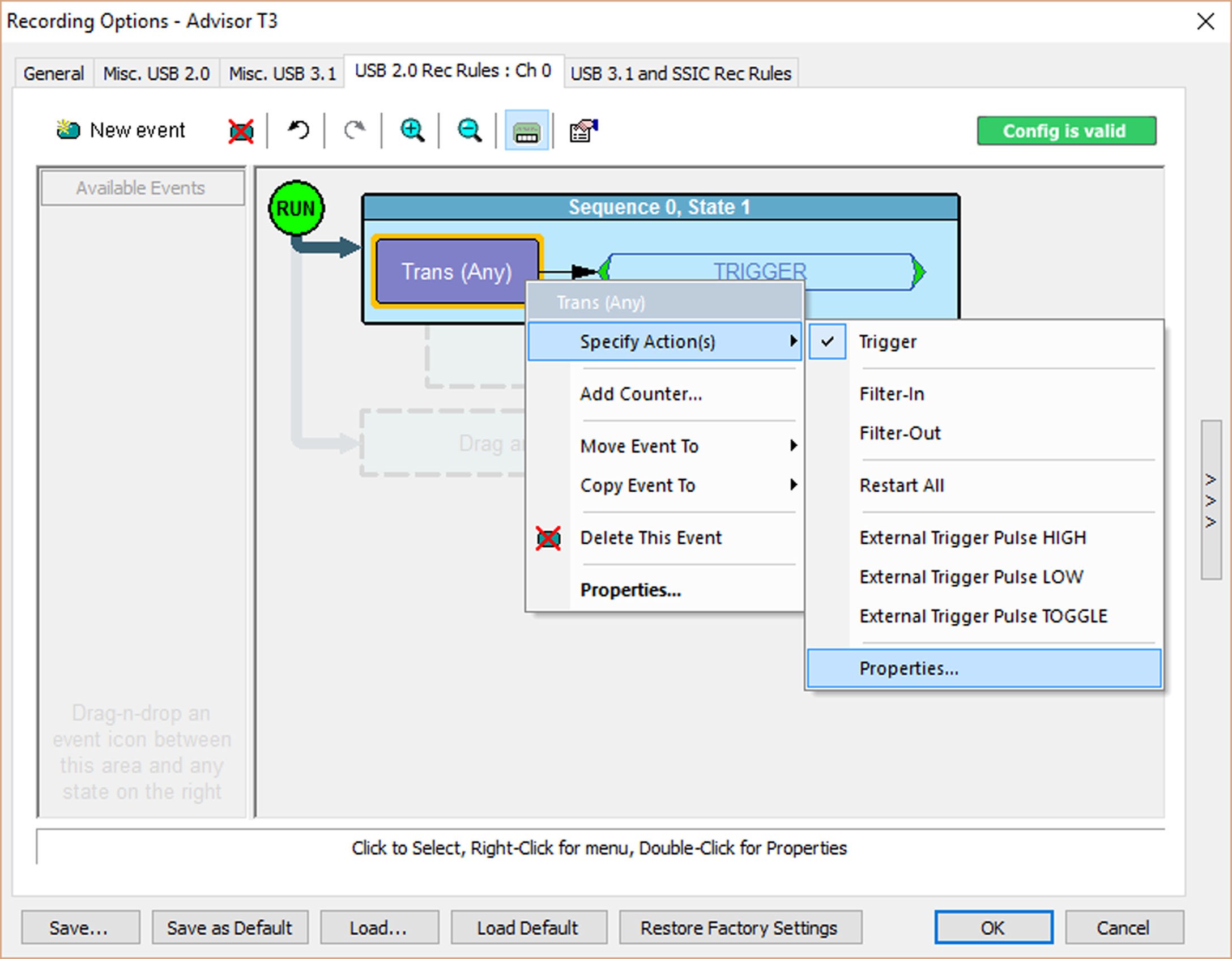
Select Specify Action, and then choose an action from the sub-menu.
NOTE: You can also set actions within the Properties dialog for each event. Double-click the Event button to open the Properties dialog, then select the Actions tab.
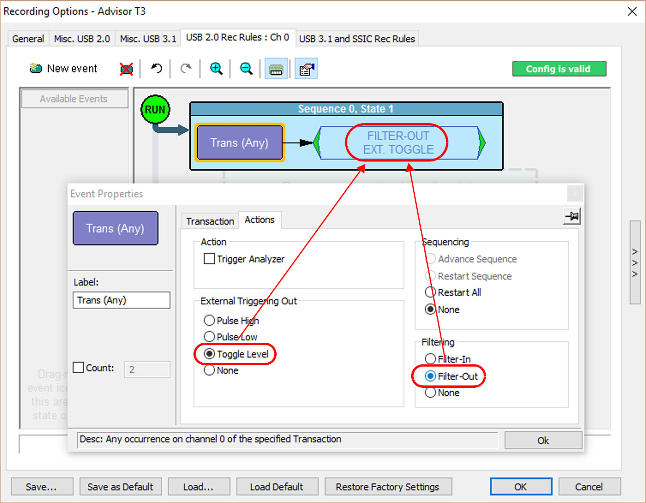
Actions and Action Properties
Actions are context-sensitive (they depend on the type of Event selected). For the Action Properties, you can set Internal Triggering and External Triggering.
Recording Rules for USB 3.2 currently do not support more than two independent states. Advance Sequence is not currently available for USB 3.2 recording rules.
NOTE: These apply to both USB 2.0 and USB 3.2, except as noted.
|
Action |
Description |
|
Trigger |
Indicates Trigger event in the captured trace file. |
|
Stop Recording |
Stops further recording once the trigger condition has been met. (USB 3.2 only) This action is active in any of the three Trigger Modes (Snapshot, Event Trig- ger, Manual Trigger). |
|
Filter-In |
Includes, in the trace file, the event specified (and no others). This action is active in any of the three Trig- ger Modes (Snapshot, Event Trigger, Manual Trigger). |
|
Filter-Out |
Excludes, from the trace file, the event specified. This action is active in any of the three Trigger Modes (Snapshot, Event Trigger, Manual Trigger). |
|
Advance the Sequence |
Go to the next state in this sequence (sequence in which this action is located). |
|
Restart All |
Restart all sequences. (USB 2.0 only) |
|
Restart Sequence |
Restart this sequence. (USB 3.2 only) |
|
Reset Timeout |
Reset the Timeout value to 0, so it starts again. (USB3.2 only) |
|
External Triggering Out: Pulse High Pulse Low Pulse Toggle |
See External Trigger Settings. Send HIGH pulse on external trigger output. Send LOW pulse on external trigger output. Send toggling signal (LOW/HIGH/LOW etc.) on exter- nal trigger output |
|
None |
No external triggering |
|
Properties |
Opens the Event Properties dialog box. |
Filter-In/Filter-Out
Filtering Start-of-Frames (SOFs) in USB 2.0 captures can inhibit the ability of the software to decode upper layers (transfer and above) properly. The SOF is used as a delimiter of traffic in the analysis heuristics, and its absence can cause a failure to recognize whether transactions should be joined into a given transfer. If you are seeing transfers that do not appear correct (for example, at the SCSI level), and you have filtered SOFs, it is recommended that you repeat the capture with filtering of SOFs turned off.
Similarly, if ITP packets are filtered from a USB 3.2 capture, it is impossible to distinguish between false and real sequence errors, so it is not recommended to filter these. If they are filtered, sequence errors should be ignored.
Filter-In and Filter-Out Example
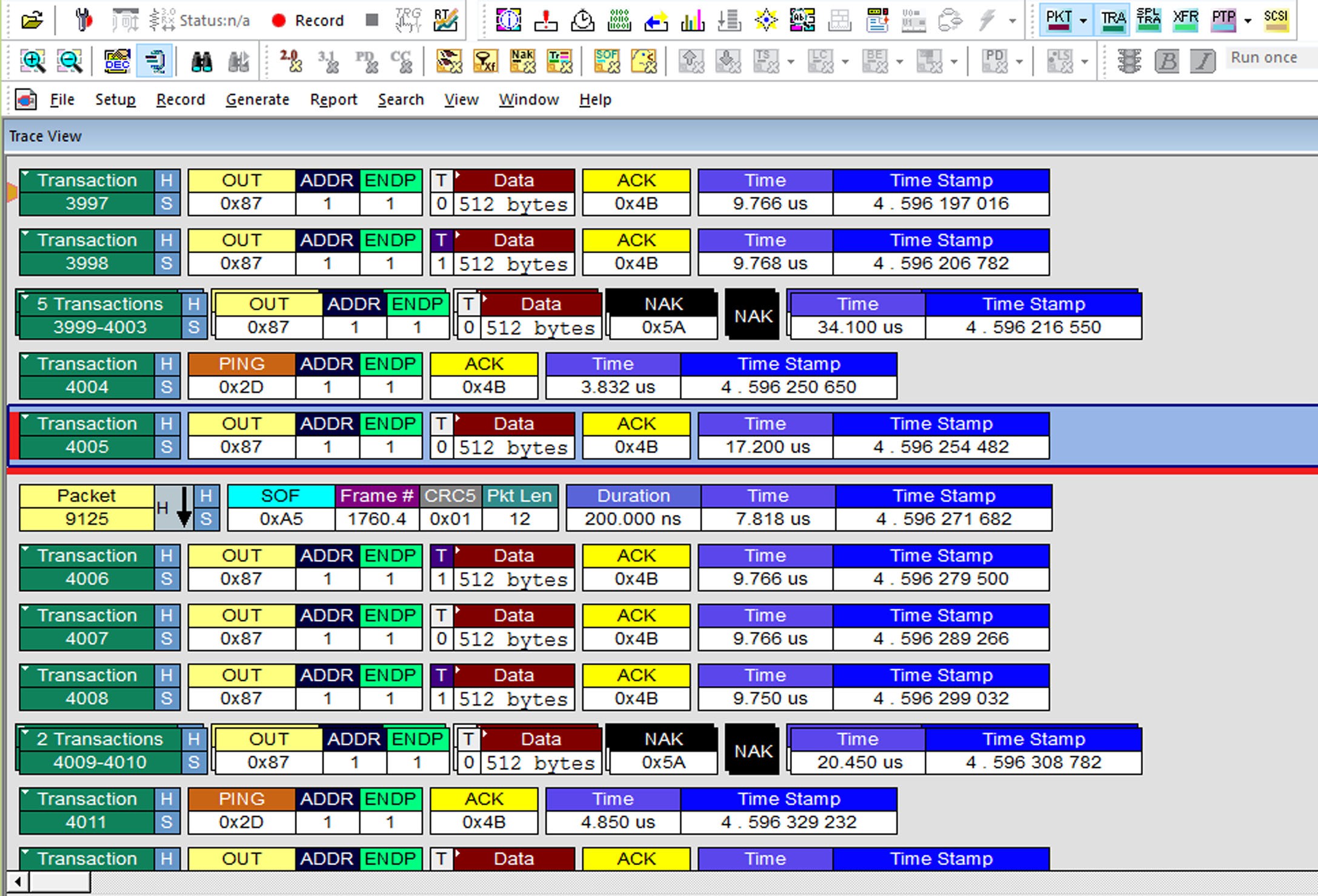
You can set the Recording Options to Filter-In Any Transactions.
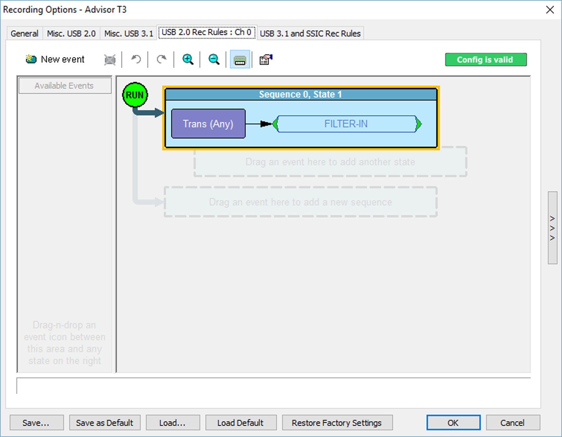
After you make a recording, the traffic shown in the Trace view will look something like the image below, depending on the type of data traffic occurring on the bus.
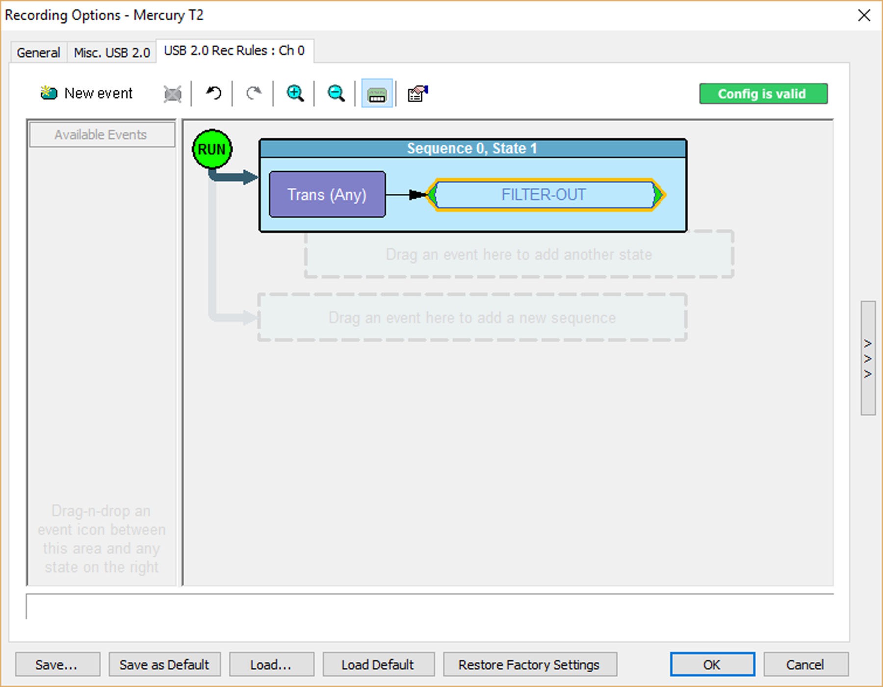
You also can set the Recording Options to FILTER-OUT Any Transactions.
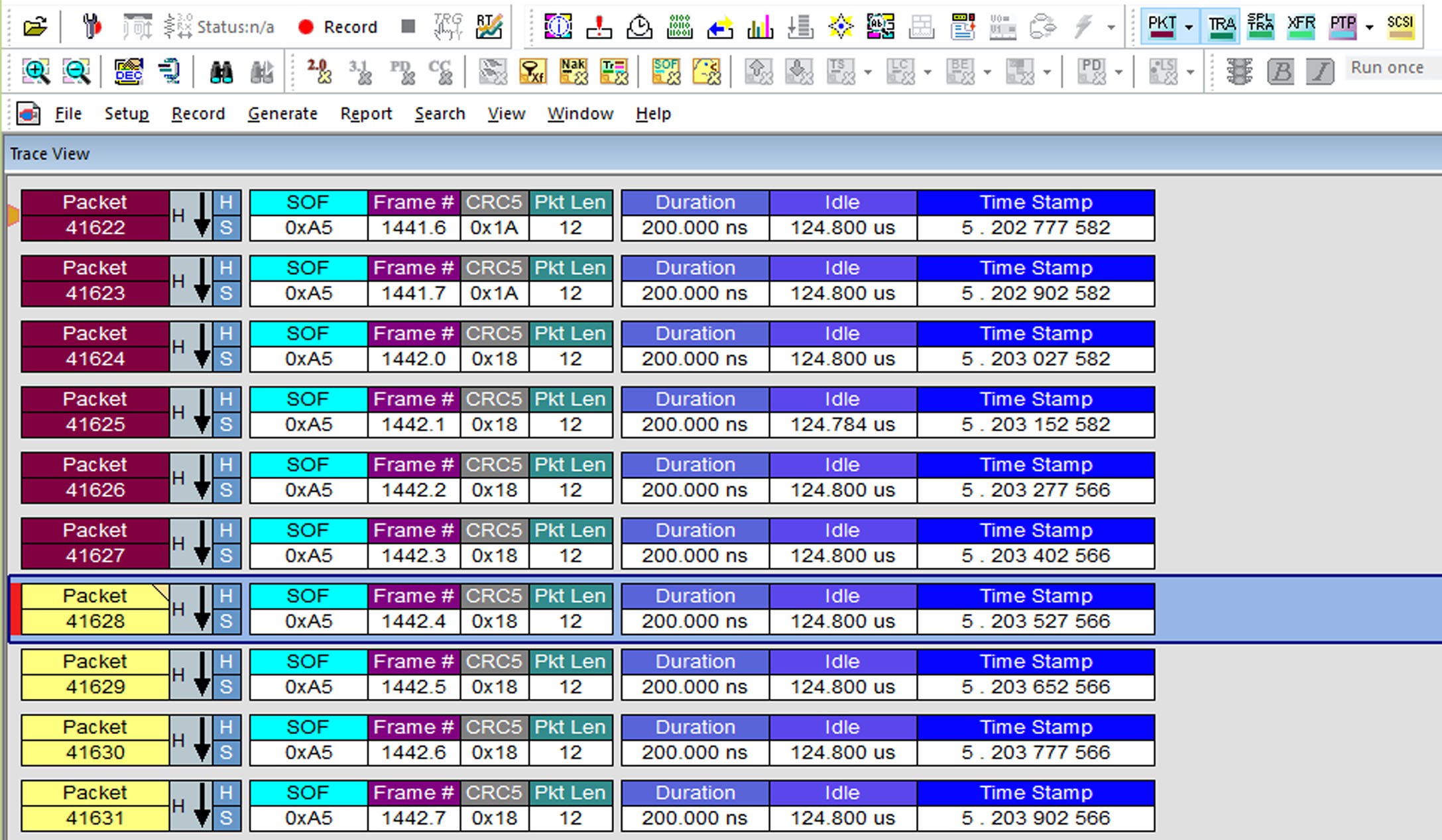
After you make a recording, the traffic shown in the Trace view will look like the image below, depending on the type of data traffic. You will see many Start of Frame (SOF) packets but no Transactions because they have been filtered out.
Trigger
Trigger position in the resulting trace cannot always be determined precisely, due to hardware limitations. In >95% of the cases, the trigger packet shown in the trace file is the one which caused the trigger. In the other exception cases, it should still always be within three packets of the actual triggering event.
Stop Recording
This will stop recording very quickly after the trigger condition occurs, but requires a small amount of post-trigger traffic before it completes. This is done so that a trigger on a packet will still allow the remaining part of that packet to be captured. For this reason, it is not recommend to use Stop Recording action for events which are not followed by any more traffic, such as Term-Off. In these cases, the recording will appear stuck waiting for the additional small amount of activity.
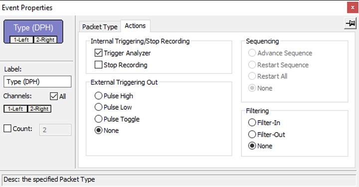
You can set External Triggering Out based on the setting in Recording Options > General > External Trigger Settings (see External Trigger Settings), Sequencing, and Filtering.
NOTE: Due to analyzer limitations in USB 3.2 capturing, some items cannot be filtered when they occur back-to-back in the capture stream. These items include small packets, such as LMP packets. When these items occur back- to-back, it can cause filtering not to work. In some cases, it can cause unexpected symbols to be captured as Inter-Packet Symbols (IPS), which cannot be decoded to real USB 3.2 packets by the analyzer software.
Events and Event Properties
USB 3.2
Recording rules are associations between events and actions. These associations determine how trace recording occurs. The supported events for USB 3.2 are:
-
Packet Type
-
Link Management Packets
-
Transaction Packets
-
Data Packet Header
-
Isoch Timestamp Packets
-
-
Data Packet (DPH+DPP) (for software version 3.70 and lower) See Data Pattern note below.
-
All Link Commands
-
Link Command Flow Control
-
LGOOD_0 through LGOOD_15 and LGOOD_n
-
LBAD
-
LCRD_A through LCRD_D and LCRD_x
-
LRTY
-
-
Link Command Link State
-
LGO_U1, LGO_U2, LGO_U3
-
LAU
-
LXU
-
LMPA
-
LUP
-
LDN
-
-
LFPS
-
Polling
-
Ping
-
Warm Reset (see Warm Reset Note below)
-
U1 Exit
-
U2/Loopback Exit
-
U3 Wakeup
-
All
-
-
Training Sequences
-
TS1
-
TS1A
-
TS1B
-
All TS1s
-
TS2
-
TSEQ
-
-
Header Pattern
-
Link Management Packet
-
Set Link Function
-
U2 Inact Tmt
-
Vndr Dev Test
-
Port Capability
-
Port Config
-
Port Cfg Rsp
-
Delay Measure
-
-
Transaction Packet
-
ACK
-
NRDY
-
ERDY
-
STATUS
-
STALL
-
DEV_NOTIFICATION
-
PING
-
PING_RESPONSE
-
-
Data Packet Header
-
Isoch Timestamp Packet
-
Deferred Header Packet
-
Delayed Header Packet
-
Custom Header Packet
-
-
Timer
-
Timeout
-
External SMA/BNC Trig In (Global)
-
SCSI
-
Primary Command Set
-
Block Command Set
-
Media Changer Command Set
-
Stream Command Set
-
Multi-Media Commands
-
Controller Commands
-
Enclosure Services
-
SCSI/ATA Transaction Command Set
-
-
USB Device Request
-
Standard Request
-
GET_STATUS
-
CLEAR_FEATURE
-
SET_FEATURE
-
SET_ADDRESS
-
GET_DESCRIPTOR
-
SET_DESCRIPTOR
-
GET_CONFIGURATION
-
SET_CONFIGURATION
-
GET_INTERFACE
-
SET_INTERFACE
-
SYNCH_FRAME
-
SET_SEL
-
SET_ISOCH_DELAY
-
-
Vendor/Class Request
-
-
Simple Trigger
USB 2.0
For Voyager, Advisor, and Mercury, the supported events for USB 2.0 are:
-
Packet Identifier
-
Token Pattern
-
SOF Pattern
-
Device Request
-
Data Pattern
-
Bus Condition
-
Errors
-
Transaction
-
Data Length
-
Split
-
External SMA/BNC Trig In (Global) (see Notes on External Trigger In below)
Notes on External Trigger In
Input threshold value for Voyager and Advisor T3 is 0.8 V.
Input threshold values for USB Tracer/Trainer are between 0.8 V and 2 V (TTL Levels).
The minimum value of the external input signal which can be input to Voyager, Advisor T3, and USB Tracer/Trainer is 0 V. The maximum value is 5 V.
Error Event Properties
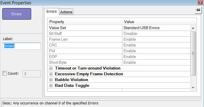
The dialog lists the Properties and their Values.
NOTE: The default values of Babble clocks and Time-out or Turnaround violation are based on the recording speed selected in the 2.0 Misc tab. If the selected speed is Auto-Detect, the defaults are based on Hi Speed traffic, since this is the most prevalent speed today.
If you change the recording speed AFTER you have defined error events, the Babble clocks and Time-out or Turnaround violation values are NOT updated, so you can get a false trigger or a missed error.
Therefore, to ensure Babble and Turnaround triggers have the correct default values, you should follow this procedure:
-
Set the Recording Speed to the explicit value you are going to be capturing (Hi, Full, or Low) in the 2.0 Misc tab. Do not use Auto-Detect.
-
Delete any error triggers from the Rec Rules tab.
-
Save your recording options as Default.
-
Close the Recording Options dialog.
-
Open the Recording Options Dialog.
-
Select the Errors trigger in the Rec Rules Tab.
-
If capturing Hi Speed, verify that the default value for Babble trigger is 7435.
-
If capturing Full or Low Speed, verify that the default value for Babble trigger is 59840.
If you always leave the speed set to a specific value due to testing the same device or class of devices all the time, the values will remain correct when you open the Rec Rules dialog.
Using Sequences
Using a Single-State Sequence
As described previously, a sequence can be single-state or multi-state. A single-state sequence is a simple combination of events and actions. You cannot create looping or branching conditions with this type of sequence.
A multi-state sequence allows you to branch successively to (advance to) lower states in the sequence or to loop to the front of the sequence (restart the sequence).
Using a Multi-State Sequence
Multi-state sequences allow you to create conditions that branch down to successive states or loop back to the beginning of the sequence. They are more complex than single-state sequences but very powerful.
Using Independent Sequences (USB 2.0 only)
You can use up to eight independent sequences. By default, they are labeled Sequence 0 through Sequence 7.
The sequences operate in parallel and have no effect on each other with the following exception:
Any of the sequences can contain the action Restart All. This action restarts all sequences in the Main Display area.