
The Recording Options General tab allows you to select or adjust the trigger mode, the buffer size, the amount of post-trigger recording, and the trace filename and path.
Product
You can select one of the following products:
-
Voyager M4120
-
Voyager M480x
-
Voyager M4x
-
Voyager M310P
-
Voyager M310e
-
Voyager M310C
-
Voyager M3x
-
Voyager M310
-
Voyager M3/M3i *
-
Advisor T3
-
Mercury T2
-
Mercury T2C
-
Mercury T2P
* No longer supported.
Analyzer vs. Exerciser vs. DP Alt Mode Analyzer
This selects the overall mode of operation of the Voyager product. (Mercury and Advisor products only run in Analyzer mode.) Voyager products can be put into Exerciser mode, where they will behave as a Host or Device based on scripts provided. They can simultaneously capture these sessions for display in a trace file. See Traffic Generation 2.0 and Traffic Generation USB 3.2, USB4, & PD Exerciser for more information on Exerciser capabilities. Voyager M4x supports the selection of DP Alt Mode Analyzer, which uses the bottom 2 Type-C connectors on the front of the M4x to capture the Display Port sideband signaling on its Aux channel. There is no support for capturing Display Port high speed traffic in this mode.
Trigger Mode
The Trigger Mode box defines how the analyzer begins and ends a recording.
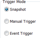
Snapshot
A Snapshot is a fixed-length recording. The size of this recording is set by the Buffer Size box. Recording begins when 

Manual Trigger
The manual trigger option can be used when you elect to initiate the recording by pressing the manual trigger button.
Recording begins when you click 
Recording ends when 
Event Trigger
Recording begins when you click 
Recording continues in a circular manner within the limits set by the buffer size until an event is detected that meets the Trigger conditions specified in the Triggering Options and the defined amount of data has been recorded after the Trigger Event.
Recording Channels
You can select a combination of USB 2.0, USB 3.2, USB4, USB4 SB, Power Delivery, and DP AUX.
Note: Only one of the USB 3.2 and USB4 channels can be enabled at a time. The analyzer must reboot to switch between these channels.
If you select different external trigger modes in the Recording Rules when performing simultaneous USB 2.0 and USB 3.2 captures, the trigger mode for USB 3.2 will be applied.
The USB 3.2 channel is used to record Gen 1 and Gen 2 traffic. Gen 2 captures are only supported on Voyager M310, M310C, M310P, M310e, M4x, M480x, and M4120.
The M310C and M310P only support the capture and display of the DisplayPort Aux channel Protocol, which runs on the SBU wires. The Mercury T2P, Voyager M310e, Voyager M4x, M480x, and M4120 support USB4 SB packet capture, as well as the DisplayPort Aux channel.
The Power Delivery Recording channel is explained in Power Delivery Recording Channel.
|
Model |
USB 2.0 |
USB 3.2 |
USB4 |
Power Delivery |
Sideband |
|
Voyager M4120 |
Yes |
Yes (Gen 2x2) |
Yes |
Yes |
Yes (DP and USB4) |
|
Voyager M480x |
Yes |
Yes (Gen 2x2) |
Yes |
Yes |
Yes (DP and USB4) |
|
Voyager M4x |
Yes |
Yes (Gen 2x2) |
Yes |
Yes |
Yes (DP and USB4) |
|
Voyager M310e |
Yes |
Yes (Gen 2x1) |
N/A |
Yes |
Yes (DP and USB4) |
|
Voyager M310P |
Yes |
Yes (Gen 2x1) |
N/A |
Yes |
Yes (DP) |
|
Voyager M310C |
Yes |
Yes (Gen 2x1) |
N/A |
Yes |
N/A |
|
Voyager M3x |
Yes |
Yes (Gen 1x1) |
N/A |
N/A |
N/A |
|
Voyager M310 |
Yes |
Yes (Gen 2x1) |
N/A |
N/A |
N/A |
|
Voyager M3i |
Yes |
Yes (Gen 1x1) |
N/A |
N/A |
N/A |
|
Advisor T3 |
Yes |
Yes (Gen 1x1) |
N/A |
N/A |
N/A |
|
Mercury T2P |
Yes |
N/A |
N/A |
Yes |
Yes (DP and USB4) |
|
Mercury T2C |
Yes |
N/A |
N/A |
Yes |
N/A |
|
Mercury T2 |
Yes |
N/A |
N/A |
N/A |
N/A |
Note: Analyzers may capture initial state events such as VBUS state, Term states, and the states of CC signals when Type-C Cables are used. Because of this, it is possible for the Recording session to capture a trace even if no cables are attached to the box; the analyzer just records the initial conditions.
Power Delivery Recording Channel
Enabling this on systems that are licensed for Power Delivery will capture the signaling over the Configuration Channel (CC) wire in the USB Type-C™ connector. This is supported on Voyager M310C/M310P/M310e/M4x/M480x, M4120, and Mercury T2C/T2P.
Connected Device Name
Enter a user-friendly name for the DUT and/or HUT so that it makes reading the Trace easier. For example, the DUT could be “Acme HD”, and the HUT could be “Cherry PC”.
The names provided here are displayed in the Trace View as Port Aliases. See Port Alias for more information.
Recording Scope (Voyager, Advisor T3 and Mercury)
Select either:
-
Conventional Single Buffer Recording: Select Buffer Size (see below). The analyzer limits the data amount captured to the selected buffer size. Use the Trigger Position slider (see below) to control the data amounts captured pre- trigger and post-trigger.
OR
-
Spooled Recording (available on certain models): The analyzer begins recording data to the analyzer memory when the record button is pressed. The entire analyzer memory is used to buffer data while simultaneously uploading the trace file to an attached storage device.
Set Recording Size Limits. If you use Snapshot, you can optionally use Record for an elapsed time or Record a number of megabytes.
If you use Manual Trigger or Event Trigger, you can optionally use the Until Triggered, plus options to enter post-trigger limits by megabytes or elapsed time. These options allow you to specify a trigger event to start the recording. When these options are used, the trigger position slider is not active. The trigger event is within the first 100 packets. The balance of the memory captures traffic occurring post trigger.
Note: You can use Snapshot, Manual Trigger, or Event Trigger trigger mode with either Recording Scope: Conventional Single Buffer Recording or Spooled Recording.
-
When capturing high bandwidth traffic with Spooled Recording, the traffic rate may overflow the system’s ability to upload data to disk. In the event of overflow, the analyzer stops the recording automatically, even if the trigger event has not yet occurred. This can occur in 3.2 traffic as well as in 2.0 traffic. The analyzer does not drop data or leave gaps in the recording. Instead, it automatically uploads all the traffic stored in memory. You must make sure that the traffic being recorded does not overrun the buffer, by either adjusting the actual data transmissions between the host and device, or by adding filters to the analyzer recording to reduce the quantity of data per second that the analyzer is capturing and uploading to the Analyzer host machine.
Buffer Size
You can adjust the size of the recording buffer from a very small size up to the maximum available in your product. The maximum values selected may be slightly smaller than the entire buffer size due to a very small amount of overhead (like you see in Hard Disk sizing).
The Trigger Mode option determines how this buffer is used. Although the analyzer has a large physical memory, the efficiency of the recording is about a 2:1 ratio of physical memory to actual USB traffic. Shorter USB packets yield a slightly less efficient recording. The non- traffic portion of physical memory is utilized for control and timing information.
Note: The scale is not linear and affords more granularity in smaller buffer sizes.
Trigger Position
You can adjust the amount of recording to be done post-trigger or select where you want the Trigger located within the defined buffer. You can adjust the Triggering Position between 1 and 99% post-trigger. Trigger Position is available only when Manual Trigger or Event Trigger is selected as trigger mode.
As an example, if the buffer size is set to 16 MB, then for the following Trigger Position settings, the amount of pre-trigger and post-trigger data is:
-
95% post-triggering: 0.8 MB pre-trigger, 15.2 MB post-trigger
-
75% post-triggering: 4 MB pre-trigger, 12 MB post-trigger
-
50% post-triggering: 8 MB pre-trigger, 8 MB post-trigger
-
25% post-triggering: 12 MB pre-trigger, 4 MB post-trigger
-
5% post-triggering: 15.2 MB pre-trigger, 0.8 MB post-trigger
Note: When a Trigger occurs, recording continues until the post-trigger amount of the buffer is filled or when Stop is selected.
Options Name
The Options Name is a descriptive label of the current Recording Options settings. Options Names are associated with files that have a .rec suffix.
The default option name is default. Default preserves the current Recording Options settings.
The purpose of the Options Name box is to give you a place to preserve different Recording Options that you use on a recurrent basis. For example, if you use two or three different Recording Options configurations, you can save these configurations and load them the next time they are needed.
Because Options Names are descriptive labels and not file names, you can enter in any text you like into the box. Your labels can be very descriptive such as “Trigger on High Speed traffic when CRC errors occur”.
To create a new Recording Options name:
-
Enter a comment for the new file in the Options Name field.
-
Click Save to display the Save As window.
-
Specify a filename (*.rec)
-
Click Save.
To load a Recording Options name:
-
Click Load to display the Open window.
-
From the list of .rec files, select the one that represents your Options Name. The options settings for that name are displayed.
Trace File Name & Path
Trace File Name & Path is the location for saving your trace file. The default recording file name is data.usb for recordings and its associated data in a folder with the same name (but with the extension .tmp). If you are recording on both channels, then the system creates two files: data_0.usb for Channel 0, and data_1.usb for Channel 1.
-
Click Trace File Name & Path.
-
Click Change Default Location to display a Specify Trace File Name dialog in which to enter the recording file name *.usb for all subsequent recordings.
Note: The serial number of the analyzer will be added to the filename if more than one USB analyzer is being used.
This is done (for example) when the desired Trace File Name & Path has such a reference in the Recording Options file.
IMPORTANT: Do not attempt to save traces on a network drive on which you do not have create or write permissions. This is not supported in the current software.
Additional Trace File Settings
The application provides the option to enter additional Trace File Settings from any available product mode. Click the Additional Trace File Settings... button under Trace Filename & Path to launch the Additional Trace File Settings dialog window. The figure below shows an example of additional settings for the Voyager M4x.
Note: If you are using multiple screens, the dialog window might appear in a different screen from the application display.
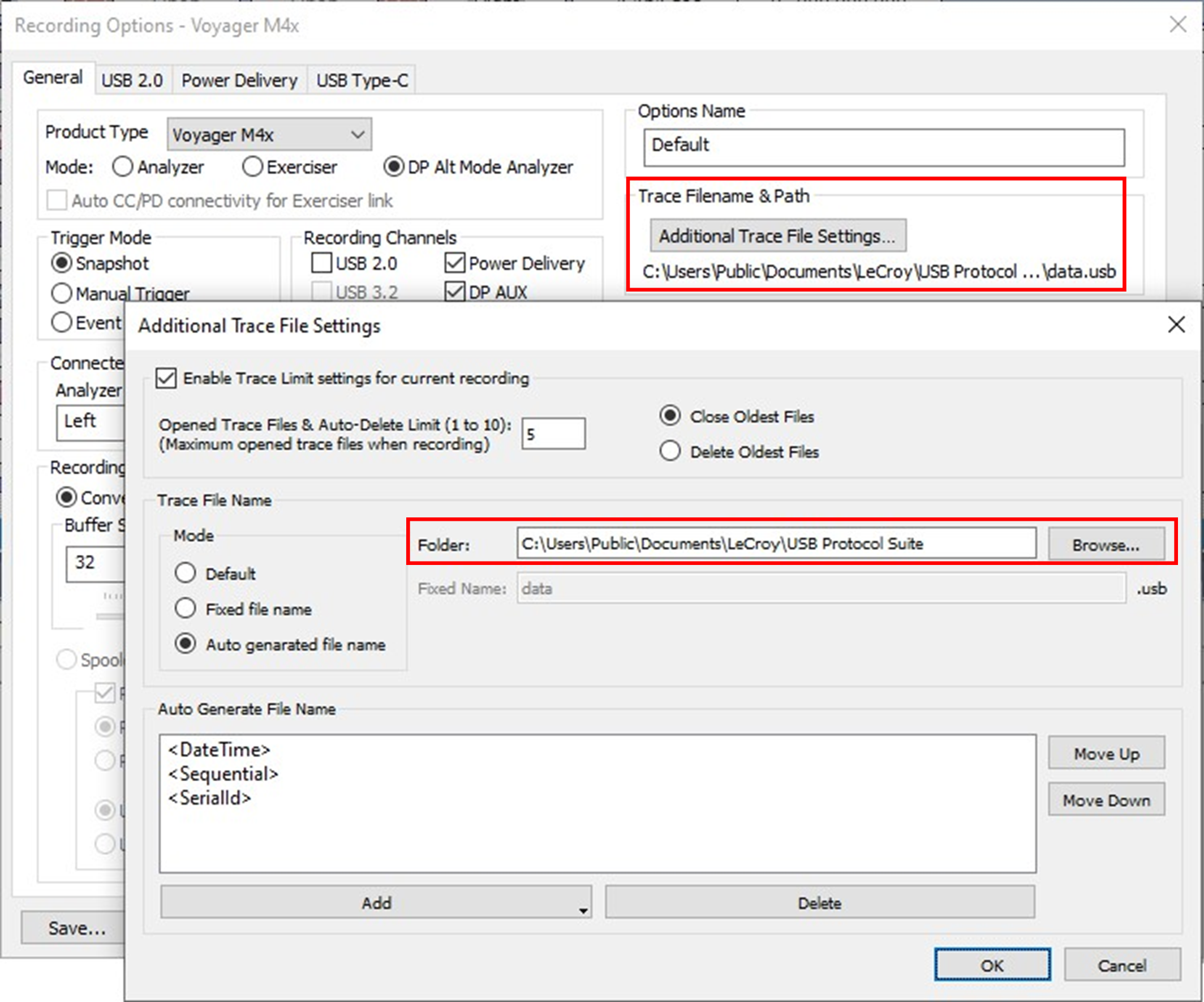
The following options are available:
Enable Trace Limit settings for current recording
-
Opened Trace Files & Auto-Delete Limit (1 to 10): Option to set the num- ber of opened files limit from 1 to 10.
-
Close Oldest Files or Delete Oldest Files: Option to either close or delete (not both) opened files over the set limit.
Trace File Name
-
Mode
-
Default: The Fixed Name is used, and will include the analyzer serial number and date/time of capture appended to the end.
-
Fixed file name: The Fixed Name is used.
-
Auto generated file name: The file name is generated based on the patterns provided in the Auto Generate File Name area.
-
-
Folder: Use the default path or click Browse... to select or enter a differ- ent folder.
-
Fixed Name: If you selected the Default or Fixed file name mode, the ini- tial text string can be defined here. The default value is “data” and the exten- sion will always be .usb.
Auto Generate File Name
-
Add button: Click the arrow in the lower right corner of this button to select the type of information you want in the file name. You can add the fol- lowing topics:
-
Text (defaults to “data”)
-
SerialId
-
DateTime
-
Sequential
-
-
Delete button: Use this to remove information you don’t want in the auto-generated file name. Select (highlight) the topic you wish to remove (e.g., <Sequential>) and click Delete.
-
Move Up and Move Down buttons: Use these buttons to organize the information in auto-generated file name. Select (highlight) the topic and click one of the buttons to arrange the file name.
USB Raw File Support
Select this box to save raw data from the capture in the form of a .usbraw file that will be created in the same folder as your trace. If you are having any problems with your captures, this file is necessary for allowing Teledyne LeCroy support personnel to debug the issue.
CATC Sync (Voyager and Advisor T3 only)
These allow you to override the normal CATC Sync behavior when two or more voyagers are connected by a CATC Sync cable.
-
Disable CATC Sync: System behaves as if no cable were attached.
-
Independent Record Stop: If checked, the boxes will start recording at the same time, and timestamps will be synchronized, but the boxes will stop recording independently (normal CATC Sync behavior is that they stop whenever either one stops.)
-
Independent Triggers: When checked, the triggers on the boxes are independent. (Normal CATC Sync behavior is that any box triggers all boxes, synchronized trigger timestamps.)
Note: The settings for all analyzers must be the same for these CATC sync overrides to work. The behavior of the systems is not defined in the case where these values are different for each analyzer. It is up to the user to select them correctly based on his usage scenario.
External Trigger Settings
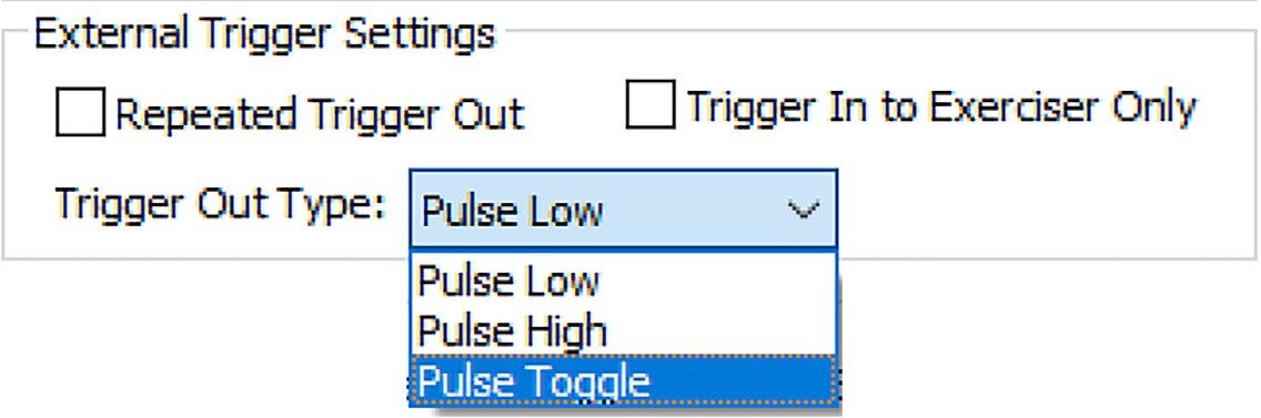
Repeated Trigger Out
In some circumstances, you will want to issue a pulse on the external trigger connection(s) whenever you see an event. By checking this box, this pulse will occur every time the event is seen, as long as it is set up as a trigger in the trigger definition dialogs. It will only be indicated once in the captured software, at the point where the first instance occurred. Events must be spaced far enough apart for the pulse to be reset by hardware, or it will not be visible on external equipment. It is safest to choose events which will occur no more frequently than once per microframe (125 uSec) Repeated Triggering.
Trigger In to Exerciser Only
Trigger In connects to exerciser only (no connection to analyzer).
Trigger Output Type
You can set the external trigger to be one of the following:
-
Pulse Low
-
Pulse High
-
Pulse Toggle
VBUS Power
You can control power settings:
-
Keep VBUS Power on after Generation/Exerciser completes: Select to keep the Host VBUS on at completion of a 2.0 or 3.2 Trainer/Exerciser script.
-
Capture Power Measurements (Voltage and Current): Records voltage and current.
-
Persistent VBUS Disconnect Button: Select to modify the behavior of the
“Momentary Disconnect” function (Invoked through the API or by the 
This can be used to turn off the VBUS for long periods of time. The normal, unchecked behavior is for the button to cycle OFF-ON automatically, with the OFF duration lasting about a half a second. This uses extra disk space corresponding to the specifications in Buffer Size for each trace.
External Interface Signals
When Save External Interface Signals is selected, saves eight bits of data from the M310s Octopus Cable (Part number AC050XXA-X) by sampling every 20 microseconds. The values are shown in conjunction with each packet displayed. The value is equal to whatever was sampled prior to the start of the displayed packet. This feature can be used along with a development system to track external events.
Capture CC Debug Info (Mercury T2C only)
The Capture CC Debug Info checkbox enables capturing of specific debug information used by Teledyne LeCroy to investigate issues with the Type-C Termination detection. This should only be checked at the direction of Teledyne LeCroy Technical Support, as it alters the normal contents of the trace data. If directed to use this, the trace should be captured, then this checkbox cleared for normal trace acquisitions.
Saving Recording Options
To complete your Recording Options settings, use the features at the bottom of the Recording Options screen. These features remain the same no matter which of the three Recording Options screens you are working in.
-
Click Save to save the currently specified Recording Options for use in future recording sessions. Any file name can be specified, though use of the .rec is recommended; if no extension is specified, .rec is added by default.
-
Click Load to load a previously saved *.rec file, thus restoring a previous set of Recording Options.
-
The Save as Default function is equivalent to the Save function, specifying the file name default.rec. Whenever you start up the Analyzer, it automatically loads the default.rec file if one exists.
-
Click OK to apply any changes and close this dialog box.
Click Cancel to cancel any immediate changes you have made and exit the Recording Options menu.