
The LeCroy USB Mercury T2P™ USB 2.0 and Power Delivery protocol analyzer is a verification system for USB development and testing. It supports USB 2.0, Power Delivery and Type-C, as well as Aux Port Display Port or Thunderbolt 3 Low Speed traffic. It is designed to record USB traffic and graphically present the logical transactions, events, and Power samples. It connects to a laptop or desktop host machine via USB 2.0. The Mercury T2P is powered by the USB Type-C cable, so no additional power cord is needed.
Components
The Teledyne LeCroy Mercury T2P analyzer package includes the following:
-
One Teledyne LeCroy USB Mercury T2P analyzer
-
Six USB cables: 2x A-C, C-B, C-uB, C-C, C-A receptacle
-
Quick Start Guide
Front Panel
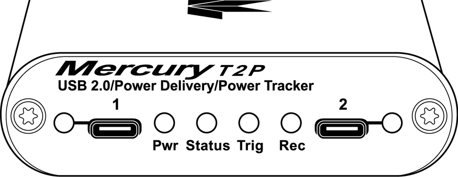
The front panel has the following indicators and connectors.
|
Indicator/Connector |
Description |
|
Connector 1 LED |
Green – Good Red – Flip it over! Solid Yellow – Special Condition |
|
Analyzer Connector 1 (downstream) |
Connects to Device under test (UFP) |
|
Power LED |
Green if on |
|
Status LED |
Blue if system successfully initializes. Red while booting. If red for more than a minute, hardware failure. Green while initializing. |
|
Analyzer LEDs Trig– Trigger Rec– Recording |
Green if triggering Red if recording enabled |
|
Analyzer Connector 2 (upstream) |
Connects to Host under test (DFP) |
|
Connector 2 LED |
Green – Good Red – Flip it over! Solid Yellow – Special Condition |
Rear Panel
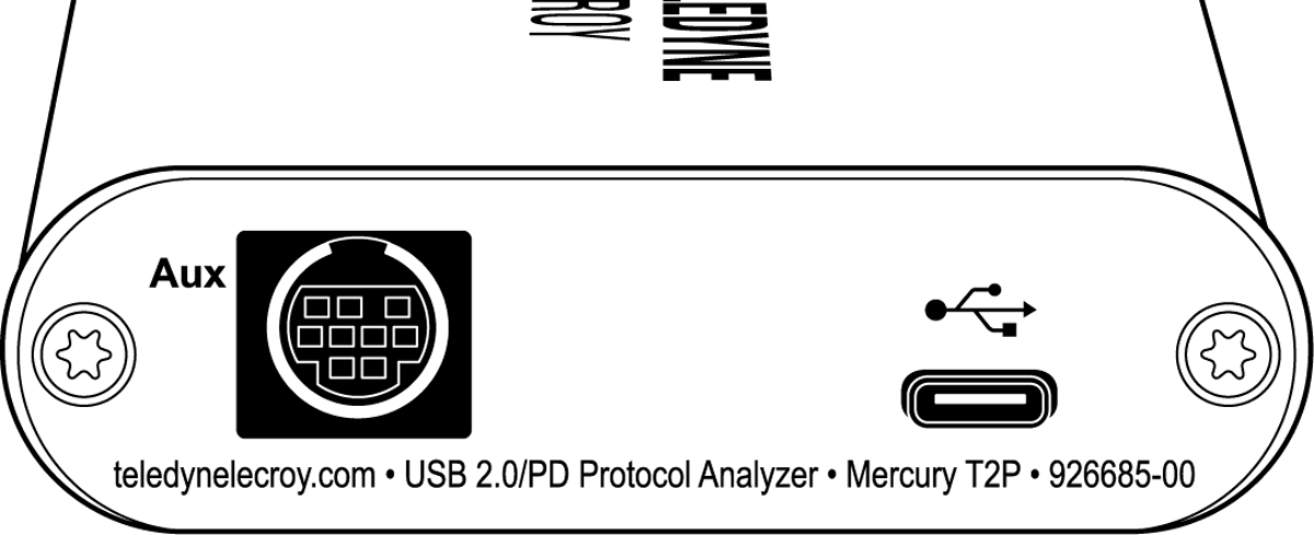
The rear panel has the following indicators and connectors.
|
Indicator/Connector |
Description |
|
USB |
Type C connector for connection to host machine |
|
Aux |
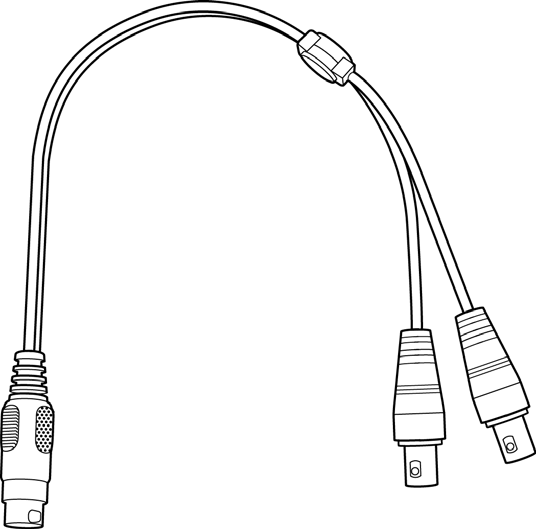
9-pin Mini DIN connector, used for External Trigger In and Out BNC connections (Cable sold separately, part # AC032XXA-X)
|
|
Trigger In |
Bayonet connector external trigger input. Note: Edge detected (Rising or Falling) Voltage required. Signal needs to be >800mV to see a logic “1”, Signal needs to be <400mV to see a logic “0”. Maximum value of the external input signal which can be input is 5 V. Minimum value is 0 V. |
|
Trigger Out |
Bayonet connector external trigger output Pulse Width = 280 ns. Pulse Voltage = 3.3 Volts into 1 MegOhms. Pulse Voltage = 2.7 Volts into 50 Ohms. Pulse is positive going |
WARNING: Do not open the enclosure. No operator serviceable parts are inside. Refer servicing to Teledyne LeCroy Customer Care.
Specifications
The analyzer has the following specifications.
|
Tool/Utility |
Specification |
|
Power Requirements |
Powered by USB Cable. 5V, 0.5 A |
|
Environmental Conditions |
|
|
Operating Temperature Storage Range Operating Humidity Operating Altitude |
0 to 50 °C (32 to 122 °F) -20 to 80 °C (-4 to 176 °F) 10 to 90%, non-condensing Up to 6560 feet (2000 meters) |
|
Probing Characteristics |
|
|
Connection |
USB 2.0 USB Type-CTM connector cables High Speed USB Connectors Standard cables |
|
Recording Memory Size |
512 MB for traffic data capture, timing, state and other data. |
Mercury T2P System Setup
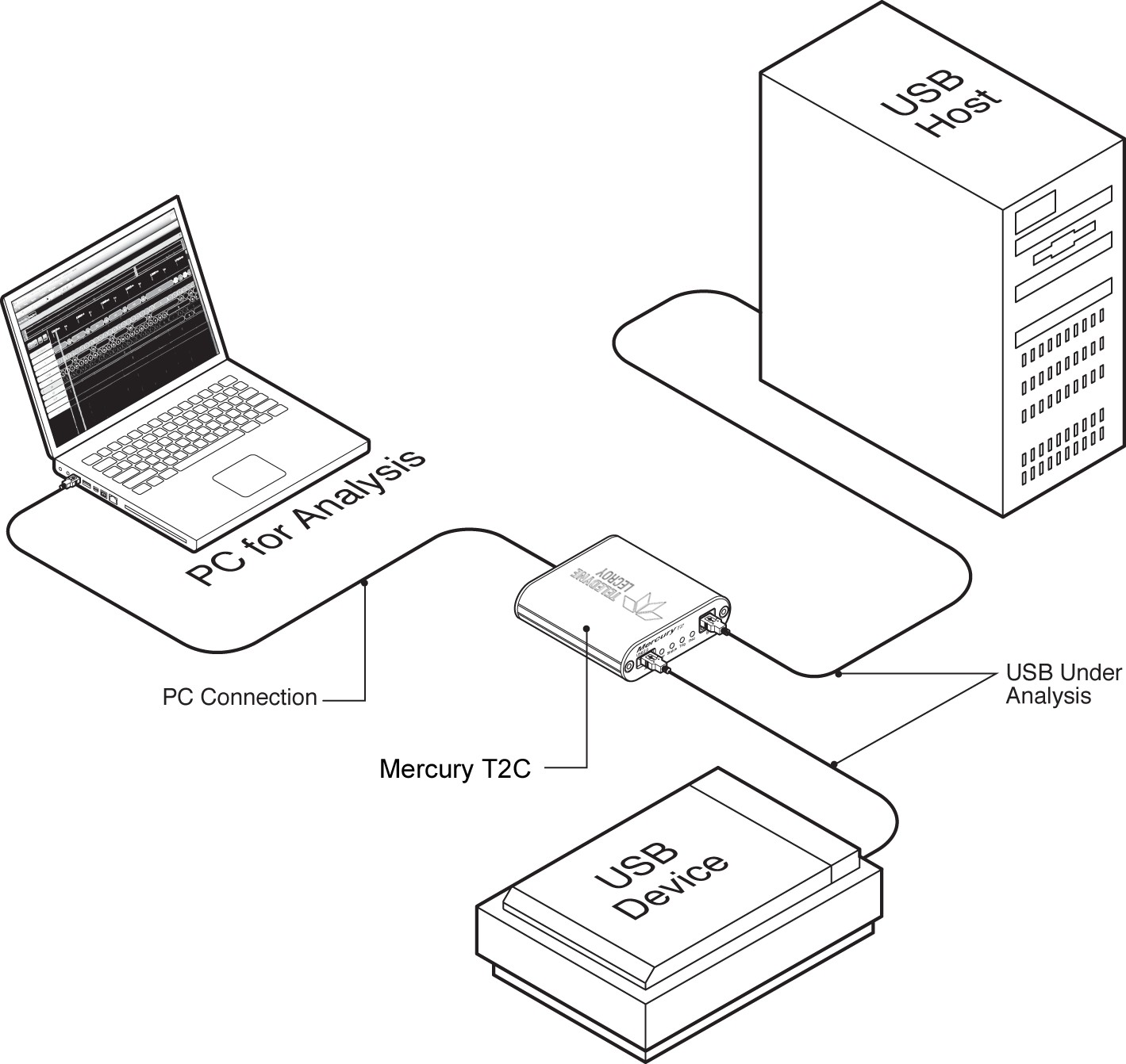
Mercury T2P is configured and controlled through a host machine USB port.
-
The Device (UFP) should be reconnected to the Connector 1 (Left side), whereas the Host (DFP) should be connected to Connector 2 (Right side).
-
The device and host should be connected to the cables before inserting into the analyzer, so the orientation and UFP vs DFP aspect can be determined.
The cables can then be connected to the Mercury T2P.
If the LED associated with the Connector shows Red, you need to flip the connector over so it shows Green. The will enable the analyzer to connect all the other signals in a 3.2 cable correctly, allowing the other SS, SS+, or Alternate Modes to work without interruption.