
System Components and Packing List
The Teledyne LeCroy Voyager M4120 analyzer package includes the following:
-
Voyager M4120 protocol analyzer/exerciser system
-
AC power cord
-
12 USB cables
-
Type-C to C 0.3m 40Gbps EPR
-
Type-C to C 0.3m 40Gbps VCONN-thru
-
Type-C to C 0.3m 40Gbps unmarked (2x)
-
Type-C to C 0.2m
-
Type-C to A 1m
-
Type-C to A 0.3m
-
Type-C to A receptacle 0.15m
-
Type-C to B 0.3m
-
Type-C to Micro-B 0.3m
-
Type-C to B 1m USB2
-
Type-C to Micro-B 1m USB2
-
-
Quick Start Guide
Host Machine Requirements
Refer to the USBProtocolSuite_Readme.pdf file from the software installation site for the current host machine and operating system requirements.
Analyzer
The analyzer is shown in the figures below.
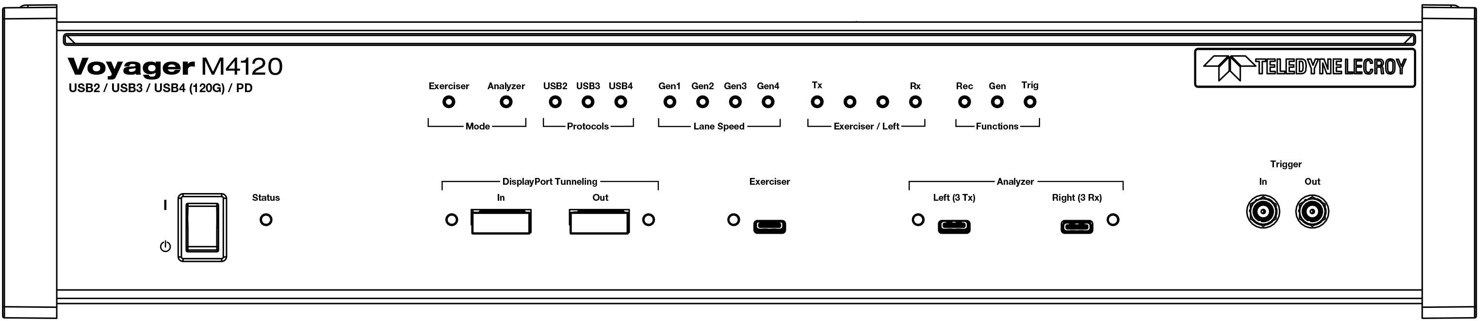
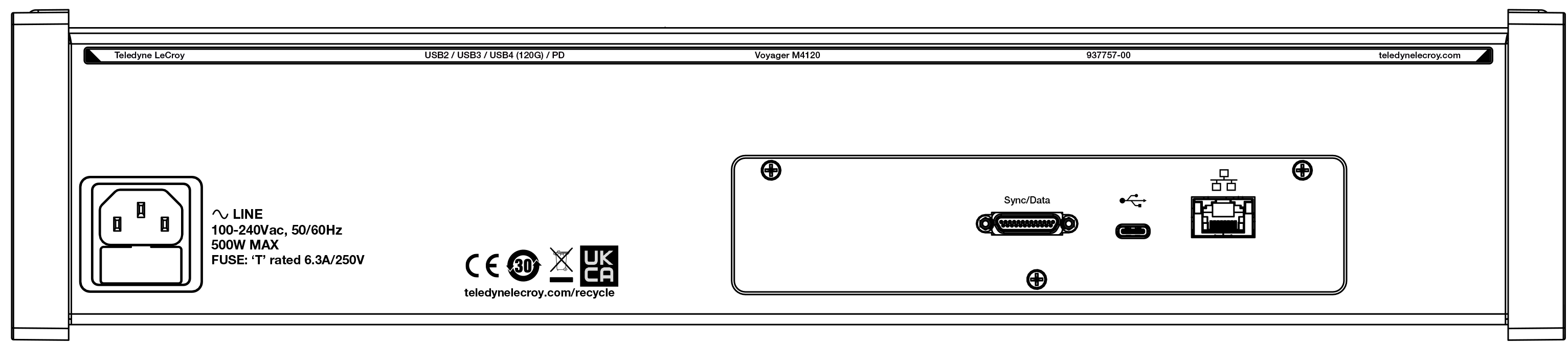
M4120 Features
The features of the analyzer are listed in the following table.
|
Feature |
Function |
|
Front Panel |
|
|
Power Switch |
( |
|
Power LED |
Green: Plugged in and powered on |
|
Status LED |
Blue: System successfully initialized |
|
Red: Hardware failure |
|
|
Green: Initializing |
|
|
Mode |
|
|
Exerciser |
Solid green: Exerciser Mode enabled |
|
Analyzer |
Solid green: Analyzer Mode enabled |
|
Protocols |
|
|
USB4 |
Solid blue: USB4 BE loaded |
|
USB3 |
Solid blue: USB3 BE loaded |
|
USB2 |
Solid yellow: FS SOFs, LS EOPs, or control endpoint traffic Slow flashing yellow: LS Traffic on endpoints other than 0 Fast flashing yellow: FS Traffic on endpoints other than 0 Solid green: HS SOFs or control endpoint traffic Flashing green: HS traffic on endpoints other than 0 |
|
Exerciser / Left (Lane configuration): These LEDs indicate whether traffic is being transmitted or received on each lane, from the perspective of the Exerciser (in Exerciser Mode) or the product connected on the Left (in Analyzer Mode). |
|
|
LED 1 |
Off: Electrical idle Solid green: Exerciser/Left is transmitting on Tx0 |
|
LED 2 |
Off: Electrical idle Solid green: Exerciser/Left is transmitting on Tx1 |
|
LED 3 |
Off: Electrical idle Solid blue: Exerciser/Left is receiving on Rx1 |
|
LED 4 |
Off: Electrical idle Solid blue: Exerciser/Left is receiving on Rx0 |
|
Lane Speed (USB4 Mode) |
|
|
Gen 2 |
Solid green: Gen 2 negotiated through SB |
|
Gen 3 |
Solid green: Gen 3 negotiated through SB |
|
Gen 4 |
Solid green: Gen 4 negotiated through SB |
|
Lane Speed (USB 3 Mode) |
|
|
Gen 1 |
Solid yellow: LFPS Slow flashing yellow: Gen 1 link is in a low power state (Ux) Fast flashing yellow: Gen 1 link training Solid green: Gen 1 link traffic (U0) Flashing green: Gen 1 data traffic (TP, DP) |
|
Gen 2 |
Slow flashing yellow: Gen 2 link is in a low power state (Ux) Fast flashing yellow: Gen 2 link training Solid green: Gen 2 link traffic (U0) Flashing green: Gen 2 data traffic (TP, DP) |
|
Functions |
|
|
Rec |
Solid green: Recording is occurring |
|
Gen |
Solid green: Exerciser is generating traffic |
|
Trig |
Solid yellow: Trigger has occurred |
|
Analyzer Connectors Left and Right |
LEDs Off: No cable attached Solid Red: Plug is upside-down; invert and re-insert Solid Green: Plug is correctly oriented |
|
Trigger |
|
|
Feature |
Function |
|
In |
SMA external trigger input Note: Edge detected (Rising or Falling) Voltage required. Signal needs to be > 800mV to see a logic “1”, Signal needs to be < 400mV to see a logic “0”. Maximum value of the external input signal which can be input is 5 V. Minimum value is 0 V. These conditions will trigger the analyzer to start recording or will trigger the action specified in Advanced Recording Options (if applicable). |
|
Out |
SMA external trigger output. Pulse Width = 280 ns. Pulse Voltage = 3.3 Volts into 1 MegOhms. Pulse Voltage = 2.7 Volts into 50 Ohms. Pulse is positive going. |
|
Rear Panel |
|
|
Sync/Data |
Used for daisy-chaining and Cross Sync, as well as 8-bit Data Capture and external Trig In/Out, with Cable (P/N AC061XXA-X) (sold separately). The 8-bit data signals use a threshold of 0.8V, with 50 mV hysteresis. The circuit is 5-volt tolerant. |
|
Ethernet |
Gigabit Ethernet for connection to host machine. |
|
USB |
USB 3.2 SuperSpeed Type-C Connector to host machine. |
|
AC IN |
100-240V AC, 500 Watt max |

WARNING: Do not open the Voyager M4120 enclosure. No operator-serviceable parts are inside. Refer servicing to Teledyne LeCroy Customer Care.
Specifications
The analyzer specifications are listed below.
|
Tool/Utility |
Specification |
|
Power Requirements |
100-250V AC, 225 Watts |
|
Environmental Conditions |
|
|
Operating Temperature |
0 to 40 °C (32 to 104 °F) |
|
Storage Range |
-20 to 80 °C (-4 to 176 °F) |
|
Operating Humidity |
10 to 90% RH, non-condensing |
|
Operating Altitude |
Up to 6560 feet (2000 meters) |
|
Probing Characteristics |
|
|
Tool/Utility |
Specification |
|
Connection |
USB4 grade USB Type-CTM connectors: The Voyager analyzer and exerciser port differential input impedance on the USB4 signal wires is between 80 and 120 ohms. USB Type-CTM connector cables High Speed USB Connectors Standard cables |
|
Power Tracker (VBUS & CC) |
Sampling interval: 20 µs (50 kHz) synchronized to protocol trace |
|
Switches |
Power On/Off |
|
Recording Memory Size |
32 GB for traffic data capture, timing, state, and other data |
Voyager M4120 Specific Setup Notes
The Type-C connectors on the front are meant to connect to Hosts (which have a DFP or Downstream Facing Port) and Devices (which have a UFP or Upstream Facing Port).
Note: Analysis of traffic requires the use of short, low-loss, high-quality cables. The cables provided, which have the Teledyne LeCroy label on them, have been verified to provide excellent signal quality. Using other cables may compromise the signal quality and prevent capturing of clean traffic.