
Device Emulation is a licensed option that allows the system to generate device-side traffic. Like host traffic generation, device emulation uses text-based generation files (.utg) to generate traffic.
Device emulation has three steps: create a generation file, configure generation settings, and then generate traffic.
Creating a Generation File
Generation files can be created one of two ways:
Write a generation script file using either Teledyne LeCroy's context-sensitive script editor or any text editor that you choose.
OR
Use a pre-recorded trace file that has the type of traffic that you want to generate. This file is a blueprint for the traffic generation script file.
If you decide to use a pre-recorded trace file as a generation blueprint:
-
Verify that the trace file contains traffic for only one device.
-
If it does not, click Setup > Level Hiding to hide all the other devices.
-
To save the file as a new file without the hidden traffic, click File Save As and select Do not save hidden packets/transactions/transfers.
Setting Generation Options
-
Set the Traffic Generation options by configuring the Misc page in the Recording Options dialog box: Setup > Recording Options > Misc
-
In the Misc page, select Device Emulation Mode.
-
Configure Resume settings:
-
If you want the simulated device to issue Resumes, then select Device Resumes and enter a delay time (in milliseconds).
-
If you do not select Device Resumes, the emulated device waits for a Host to issue a Resume.
-
If you want the simulated device to take its address from the Traffic Generation (.utg) script file, select Use Address in .utg file. This option causes the system to read the .utg file and assign a Device Address based on the device traffic that it sees in the file.
-
-
Click OK to close the Recording Options dialog and apply the changes. The generation settings take effect as soon as you execute a script.
NOTE: The Device Emulator does not look at the Set Address in the script, so if your host controller is running more than one device, it may enumerate your device emulator incorrectly when you begin to generate traffic. The solution is to manually assign a device address. To manually configure the Device Address, select Emulated Device's Hex Address and enter an address or mask. A mask allows the system to respond to multiple device addresses.
Frame Duration Customization
USB2 generation script provides capability to modify frame duration for special verification purposes. To achieve variation of the frame time, the script should manipulate the idle bit times. Using empty frames always creates standard frames; using “Frame=auto
{idle=to_eof}” also creates a standard frame, but using “idle=<n bits>” allows you to vary the frame duration. The figure below shows a sample script.
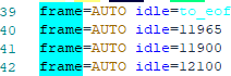
The script shown above creates 2 frames of standard duration, because “to_eof=11965” makes lines 39 and 40 functionally the same. Line 41 creates a frame 10% short; line 42 creates a frame 10% long. The figure below shows idle time field in the generated trace view.

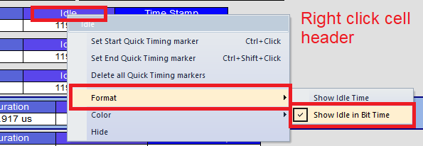
Tip: You can change the idle time field to show “Bit Time” instead of time to help calculate the number of bits needed manually. See images below for examples.

Instead of ending the packet declaration as “idle=to_eof” you can change “to_eof” to a number of bit times.
-
If you want to extend or shorten a frame, use a number of idle bits after the last packet before the next SOF instead of the “to_eof” automatic calculation.
-
If you want to drop one or more SOF, add more idle=12000 between SOF. A FS frame has 12000 bit times normally; however, also remember that no SOF for >36000 bit times should cause the device to go to suspend state.
Run the Traffic Generation Script File
-
Connect the system port B (either Hi Speed or Classic Speed) to the Host.
-
Open the Traffic Generation .utg file.
-
Click

-
When execution begins, the system reads the entire generation file and parses the generation commands into groups according to their endpoints. Each of the parsed groups of commands are then written into dedicated memory segments in the generator. Up to eight memory segments can be created for the various endpoints. In the case of Endpoint 0 or any Control endpoints, a single memory segment is created.
-
Each memory segment can be thought of as a queue of the commands and responses for a particular endpoint that occur in the generation file.
-
Commands are stored sequentially within each memory segment as they occur in the generation file. For example, if a generation file has a sequence of command X and Y for the Endpoint 1, the commands are extracted in this order and placed in the Endpoint 1 memory segment.
-
When the host calls for a particular device endpoint response, the first command listed in that endpoint memory segment executes. With each sub- sequent call to the same endpoint, commands execute sequentially down the list as they occur in the memory segments. For example, if three calls were made to Endpoint 0 IN, the first three commands in that endpoint memory segment execute.
NOTE: Each of the endpoint memory segments execute independently; there are no behavioral interactions between individual endpoints.