
Note: The graphical editor supports USB 3.2 exerciser but is not currently available for PD/USB4.
The Graphical Scenario Editor allows you to create Host Emulator scenarios (only), using high-level constructs and graphical elements. After inserting an item, click on an element you wish to modify, then use the simple edit boxes and drop-down lists.
You can insert the following items:
-
High-Level SCSI Commands (SPC-3, SBC-2, SMC-2, SSC-2, MMC-5, SCC-2, and SES-2)
-
High-Level Task Management Functions
-
Bus Enumeration / Control Requests
-
Settings
-
Mass Storage Transfer Packets
-
Instructions (Start Loop, End Loop, Delay, Stop Exerciser)
After you create a new graphical scenario, use the following steps to edit or build the scenario.
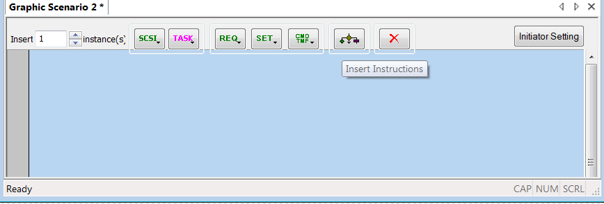
Graphical Scenario Window
The Graphical Scenario window contains SCSI, TASK, REQ, SET, Insert Instructions, and Delete Selected Item buttons.

-
SPC-4
-
SBC-3
-
SMC-3
-
SSC-4
-
MMC-6
-
SCC-2
-
SES-2

-
Abort Task
-
Abort Task Set
-
Clear Task Set
-
LUN Reset
-
Clear ACA
-
Query Task
-
Query Task Set
-
I T Nexus Reset
-
Query Asynchronous Event

-
Bus Enumeration
-
Device Requests:
-
Clear Feature
-
Get Configuration
-
Get Descriptor
-
Get Interface
-
Get Status
-
Set Address
-
Set Configuration
-
Set Descriptor
-
Set Feature
-
Set Interface
-
Set Status
-
Synch Frame
-
Set Sel
-
Set Isoch Delay
-

-
ErrLostLGOOD
-
ErrWrongLGOOD
-
ErrLostLCRD
-
ErrWrongLCRD
-
ErrCorruptLinkCmd
-
ErrCorruptLMP
-
ErrDisparity
-
ErrWrongSymbol
-
ErrLBAD
-
ErrLostLGOODAdv
-
ErrWrongLGOODAdv
-
ErrLostLCRDAdv
-
ErrWrongLCRDAdv
-
SetLinkState

-
Command
-
Task Management

-
Start Loop
-
End Loop
-
Delay
-
Stop

-
Click item for single selection.
-
Use Ctrl, Shift, or Ctrl+ A, or drag mouse around item(s) for multiple selections
Initiator Setting

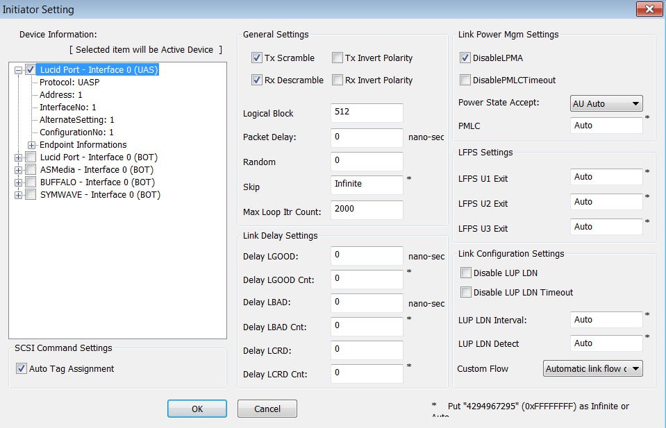
Device Information
The left pane shows Device Information, as expected from enumeration, so this pane shows general device information from a pre-configure file. The Device Information DeviceInfo.cfg file is in the Generation directory under the users directory. You can edit this file.
For each device, the following information is in the DeviceInfo.cfg file:
-
Name
-
Protocol (UASP or BOT)
-
Address
-
InterfaceNo
-
AlternateSetting
-
ConfigurationNo
-
Endpoint Information
-
EndpointNo
-
Direction (IN or OUT)
-
Max Burst Size
-
PipeUsageId
-
Endpoint Type (only for UAS protocol)
NOTE: You can only select one device from the Device List as the active device. Required information for the project is defined by the active device. The active protocol in the project is defined by the active device.
-
If you have already inserted some items in the project, and you change the active device, if the new active device is in another protocol (UAS or BOT), the software will try to convert all information to the selected protocol (based on the active device), and information may be lost.
-
If your scenario enumerates a device, you will have to issue a "SetLinkState" at the end of it to bring the link back to its initial state before running it again.
SCSI Command Settings
Auto Tag Assignment: You can choose Auto Tag Assignment for SCSI Commands. Then the tag will be assigned automatically for SCSI Commands (starts with 1 and continually increments). If you deselect this feature, you must check the tag value of all SCSI Commands in the project and make them unique in each run.
General Settings
The middle pane has General Settings: Tx Scramble, Rx Descramble, Port Configuration Ack, Tx Invert Polarity, and Rx Invert Polarity checkboxes.
You can set Logical Block Size, Packet Delay, Random Seed, Skip Timer, and Maximum Loop Iteration Count.
Link Delay Settings
The middle pane has Link Delay Settings: Delay for LGOOD, LGOOD Count, LBAD, LBAD Count, LCRD, and LCRD Count.
Link Power Management Settings
The right pane has Link Power Management Settings. You can disable LPMA and PMLC Timeout. You can set Power State Accept and PMLC Timeout.
LFPS Settings
The right pane has LFPS Settings. You can set Exit TBurst for U1, U2, and U3.
Link Configuration Settings
The right pane has Link Configuration Settings. You can disable LUP LDN and LUP LDN Timeout. You can set LUP LDN Interval and Detect Timeout.
You can select a Custom Flow Control, such as Automatic Link Flow Control, No LGOOD Detect, No LCRD Detect, No LGOOD Generation, No LCRD Generation, or No Flow Control.
NOTE: A value of 4294967295 (0xFFFFFFFF) indicates that a default value will be used (Infinite or Auto).
Option Button

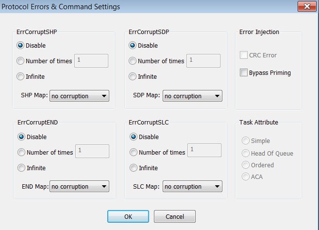
ErrCorruptSHP section has Disable, Number of items, Infinite, and SHP Map (no corruption or Corrupt Symbol 1, 2, or 3).
ErrCorruptSDP section has Disable, Number of items, Infinite, and SDP Map (no corruption or Corrupt Symbol 1, 2, or 3).
ErrCorruptEND section has Disable, Number of items, Infinite, and END Map (no corruption or Corrupt Symbol 1, 2, or 3).
ErrCorruptSLC section has Disable, Number of items, Infinite, and SLC Map (no corruption or Corrupt Symbol 1, 2, 3, or 4).
Error Injection section has CRC Error or Bypass Priming.
Task Attribute section has Sample, Head of Queue, Ordered, and ACA.
Script Scenarios
For some special purposes in which graphical scenario features are limited, you can convert a graphical scenario to a script scenario, which you can then modify.
NOTE: The software does not support converting a text scenario to a graphic scenario.
Save
-
To save a created project, select File > Save.
-
To run a saved project, select Generation > Run Scenario or use the Run Toolbar.
Copy SCSI Operation from Trace File and Paste to Exerciser Scenario
To select a SCSI command from a trace file to use in an Exerciser scenario:
Right-click any SCSI packet and select Copy to Exerciser from the menu:
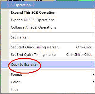
Go to the Graphical View of the Exerciser, right-click in the view, and select Paste.
NOTE: The Copy to Exerciser function only copies to USB 3 Exerciser scripts (.usb3g). Due to limitations in the USB 2.0 generator architecture, .utg files cannot accept high-level functions such as SCSI operations.
Graphical Toolbar
The Graphical toolbar contains buttons for zooming, wrapping, and converting from a graphic scenario to a text scenario:
|
Button |
Functionality |
|
Button |
Functionality |
|---|---|---|---|---|
|
|
Zoom In |
|
|
Zoom Out |
|
|
Wrap |
|
|
Convert from graphic scenario to text scenario |


